Origins and Early Development
On October 31, 1917, a memorandum signed by F.E.T. Hewlett, on behalf of the Inspector, Technical Department (TIN Section), was sent to the Air Committee’s Technical Department Inspector, Major John Buchanan. The memorandum requested the Air Committee to place a contract with Phoenix Dynamo Manufacturing Co Ltd, Bradford, for the design and manufacture of aircraft details for two experimental F.3 flying boats, whose hulls were subsequently to be built at May, Harden & May Ltd’s Kingston Bridge Works in Hampton Wick on the River Thames.
Approval was granted in accordance with British official prescription No. 256, and on November 12, Sir William Weir, Inspector of Aircraft Supplies, was notified of the committee’s decision. Three days later, Phoenix was instructed to not only proceed with the design of the aircraft details but also to prepare for the production of the complete aircraft. Drawings of the hulls were sent, and Phoenix, in particular, was required to improve the aerodynamic performance of the standard F.3, while keeping the wing roots exactly as on the current machine so that the bracing structure would be interchangeable with the standard design, and to simplify the machine’s construction for ease of manufacture.
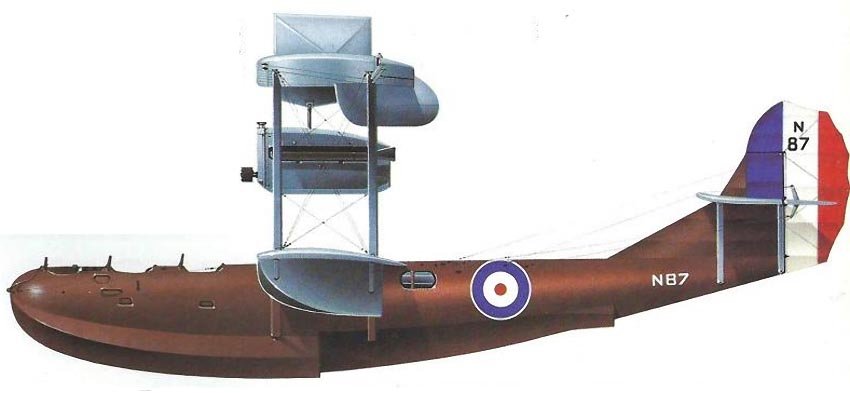
Contract number AS 37016/17 was signed on November 28, and serial numbers N86 and N87 were allocated to the two flying boats. Phoenix assigned the flying boats the designation P.5; the name “Cork” was not used until approximately June 1918. It was assigned after the Technical Department issued Instruction 538 (later 547 AP), which regulated aircraft nomenclature. The Corks were included in the category of aircraft with more than one engine and a total flight weight of 11,000-20,000 pounds (4989.6-9072 kg), named after coastal towns in Scotland and Ireland.
The P.5 was the result of the Admiralty’s decision to build a large twin-engine flying boat to meet the requirements of specification N.3B (later known as RAF Spec XXX), which the Admiralty’s Air Department formulated in early 1917. The Admiralty needed a flying boat for anti-submarine patrol with displacement and characteristics similar to the Felixstowe flying boat designed by Porte. The Admiralty also decided that the P.5 should have a hull designed by Lt Cdr Linton C. Hope, after which May, Harden & May was authorized to build two hulls based on his monocoque construction principles. This type of construction proved to be extremely strong, resilient, and allowed the hull to have a good streamlined shape. Linton Hope’s hulls were typically covered with two layers of narrow planks. The inner layer was arranged diagonally, and the outer longitudinally, riveted at wide intervals to numerous stringers, which in turn were attached to almost circular frames built into a keel extending from bow to stern. The planing bottom was constructed separately and had a similar design.
Hull Design and Construction
Production of the hulls, which were not identical, began in late 1917. Construction of the first hull (N86) was most likely completed soon thereafter, before April 11, 1918, when Maj A.J. Miley, Assistant Inspector of the Technical Department (Design), informed Phoenix of the measured weight and center of gravity of the hull; the second hull (N87) was completed slightly later. The first could be distinguished from the second by its planing bottom, which, although interrupted by the main step, extended aft to a rear step, whereas the second planing bottom had a forward step and a small, streamlined rear step attached to the main hull. The chine line of the rear step was formed by an outer skin strake that was continuous with the upper part of the front surface’s keel deck.
(R & M No.461: The first hull was numbered P.5, and the second P.5A; Phoenix used N86 and N87 respectively. However, the order in which the hulls were to be used was ultimately reversed: hull N87 was installed on the P.5, and vice versa). The main structure of both hulls was identical, and each had openings at the top for a nose gunner, tandem-seated pilot and co-pilot, and an engineer. Narrow hatches were provided for two gunners, closing with removable doors that had glazed portholes, although at one stage Linton Hope planned to place the rear gunner in the upper part of the hull. Openings were also provided in the upper sides of the hull for the lower wing’s center-section spars.
The hull skin consisted of two layers of mahogany boards, separated for waterproofing by a layer of oiled fabric. The outer layer was fastened longitudinally and was 5/32″ (3.97 mm) thick, while the inner layer was laid diagonally and was 5/16″ (7.94 mm) thick; they were secured with copper nails and passed through 3/8″ (9.53 mm) square spruce battens or hoops spaced 1 3/4″ (44.45 mm) apart. Their ends were inserted into an elm keel and glued to 35 spruce stringers with a cross-section of 1½” × ½” (38.1 mm × 12.7 mm), which were uniformly distributed around the hull’s periphery and attached to almost circular frames, spaced 2-3 feet (0.61-0.91 m). The frames were attached directly to the top of the keel, and a pair of steam-bent elm beams of rectangular cross-section were joined by mortise and tenon joints alternately to the upper and lower parts of the hull. The lower part of the hull was reinforced with short square spruce planks that passed through the keel and were known as ‘floors’.
The front part of the planing bottom of each hull had two separate layers of mahogany, separated by oiled fabric. The inner diagonal planking was 3/32″ (2.38 mm) thick, and the outer was 3/16″ (4.76 mm). The fastening method was similar to that used for the main hull, but with plywood transverse bulkheads that created a series of watertight compartments. The rear part of the first hull’s planing bottom was constructed similarly; the thickness of the outer and inner planking was 5/64″ (1.98 mm) and 5/32″ (3.97 mm) respectively. The planing bottom installed on the second hull was slightly larger than the rear step fairing and was also of Linton Hope’s design. The first hull was delivered by road from Hampton Wick to Bradford shortly before the end of April 1918, and the second followed soon after, beginning its journey north on Wednesday, May 8. According to records, the total production time for the two hulls amounted to 31,348 man-hours.
Meanwhile, on April 9, May, Harden & May delivered hull models, made under contract, to the Technical Department, where they were personally received by Linton Hope. These models were made at NPL and used for comparative wind tunnel tests, the results of which were published in R & M No.461. The research revealed that the first hull, or P.5 (N86), had significantly less drag at all speeds than the second hull, or P.5A (N87). A modified P.5 hull was also tested; it was found to also have less drag compared to the P.5A and was even slightly better than in its original form.
Despite the superiority of the P.5, which was reflected in the characteristics of the complete flying boat, upon arrival in Bradford, it was placed in storage, and the P.5A hull was used for its intended purpose. The reason for this change remains unclear, but it may stem from November 1916, when R & M No.300 “Experiments with Models of Seaplane Floats, Eleventh Series” was published. This report detailed hydrodynamic tests on hull models similar to the P.5. Various changes were made to the hull, and its shape became similar to the P.5A. This hull had better seaworthiness due to reduced spray reaching the upper hull/wings/tail. It seemed that the P.5 hull was disregarded in favor of the P.5A due to poorer seaworthiness. It is assumed that the P.5 hull was built for comparative full-scale trials.
Flight Trials and Operational Insights
By spring 1918 in Bradford, the aircraft details designed by W.O. Manning were nearing completion. These structures were made under the guidance of the Technical Department, which checked and approved Manning’s calculations and made recommendations where necessary. Information about a structural example appeared on March 11, 1918, when Solly Brandt from the Structures & Stability Section informed Cdr Alec Ogilvie, of the Technical Department (Design), about the strength of the wing spars, interplane struts, and bracing wires, which were deemed satisfactory except for some incomplete control linkages. In accordance with Phoenix’s policy, driven by P.J. Pybus and Prime Minister Lloyd George, all design elements were developed to allow for the employment of female labor, which was to be used wherever possible. This policy was applied to the production of wooden and metal components, minimizing finished components and standardizing parts for mass production and interchangeability.
The wings, of unequal span, were made in separate sections. The upper wing consisted of three parts, its outer sections attached by streamlined intermediate king-post struts located above the outer interplane struts. The lower wing consisted of four parts, two of which formed the center-section; its spars on N86 passed through the hull. Although a similar arrangement was intended for N87, this wing was made in one piece and attached directly to the upper part of the hull; the joints were faired. Each wing had two box spars made entirely of spruce; the spar flanges were separated by webs and caps, joined to them with screws and glue. To reduce wear, the caps could be made from a series of short, spliced sections, the number of which was strictly controlled. The ribs had an RAF 14 airfoil and a Warren truss construction. Three-ply birch plywood was used for the leading edge skin of the lower wing to protect it from spray damage.
Walkways on the lower wing’s center-section were also used by the flight engineer for starting and servicing the engines. Internal wing bracing was achieved by tie rods and tubular steel struts. The interplane struts and engine struts were made from thin-walled steel tubes, covered with wooden frames featuring three-ply plywood at the leading edge and fabric for a more streamlined shape. Mahogany or walnut patches were installed on the spars at the joints with all struts and with the external streamlined bracing wires for reinforcement. Both wings had fabric covering, laid diagonally in wide strips and sewn to the ribs in the usual manner. Ailerons were installed only on the upper wing, each made in two parts and hinged to an auxiliary spar. The N86 wingtip floats were identical to those installed on the Felixstowe F.3; the N87 floats were slightly deeper.
The tailplane structure was similar to the wings but had an inverted RAF 15 airfoil and was made in two parts, joined at the centerline. The tailplane halves were connected to the hull by four streamlined tubular struts. For the spar flanges, three-ply plywood was used instead of spruce; otherwise, the materials used were the same as those for the wings. The tailplane’s angle of incidence could be changed on the ground by moving two bolts. The rudder had characteristic horn balance compensation and a mixed wood and steel tube construction. The fin was easily removable for covering or transport.
For propulsion, two 360 hp Rolls-Royce Eagle VIII engines were specified and installed on both flying boats; the engine mounts were similar to those used on Felixstowe machines. Both engines were fully enclosed in cowlings made from flat aluminum panels with wooden backing. Under the center-section were three main fuel tanks. Two Rotoplunge windmill-driven pumps supplied petrol to two 20 Imperial gallon (90.92 l) gravity fuel tanks, located below the upper center-section. The fuel system was duplicated, and one or both engines could be started from either gravity fuel tank. The engine throttle control was the subject of British patent No. 122.996, obtained by Manning on July 17, 1918. It consisted of a single lever that controlled both throttles simultaneously.
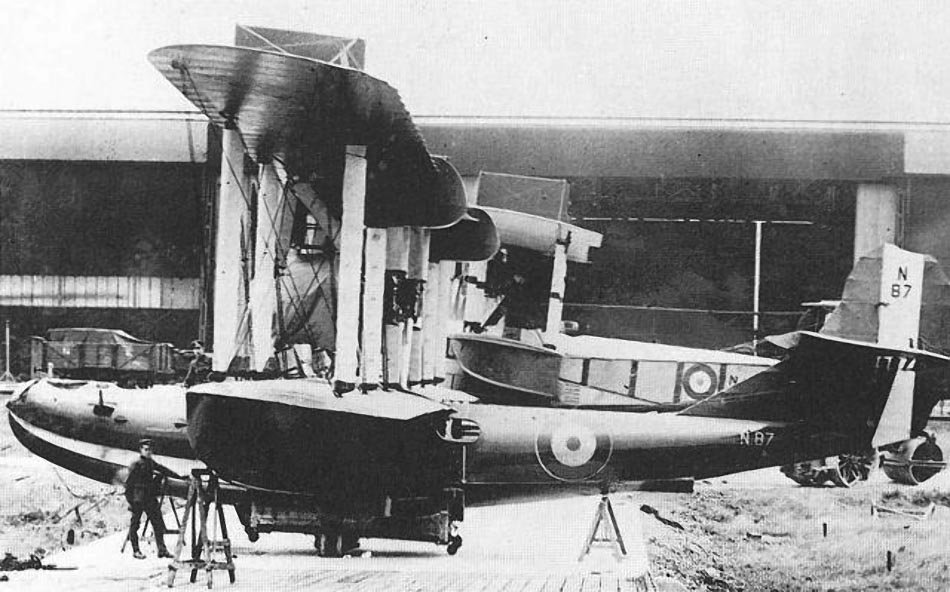
The flying boat’s main armament consisted of four 230-pound (104.33 kg) or two 520-pound (235.87 kg) bombs, suspended under the inner sections of the lower wing, and five Lewis machine guns: one in the nose in a Scarff ring mounting, one machine gun installed on each side of the cockpit on support beams for the pilot and co-pilot, and one on an arc mounting at a narrow hatch on each side of the hull. On the trailing edge of the N87’s upper wing, two additional small gondolas were installed, each equipped with one Lewis machine gun. In August 1918, Phoenix was asked to explore the possibility of placing 520-pound (235.87 kg) bombs inside the hull, but these proposals did not materialize.
On July 5, 1918, the Technical Department was notified of the completion of N86, and permission was requested to move the flying boat to Brough at the mouth of the River Humber. Exactly one week later, another letter was sent stating that “the P.5 will be ready for shipment shortly.” The next day, permission was obtained, and N86 was soon dispatched by road to Brough. Some parts, including various tail unit struts and engine cowlings, were sent by rail. The transport took place on July 26 and 27. Before the completion of N86, Phoenix requested that pilot Clifford B. Prodger be engaged for initial trials. On July 4, the Technical Department agreed, provided that subsequent test flights would be carried out by Major M.E.A. Wright.
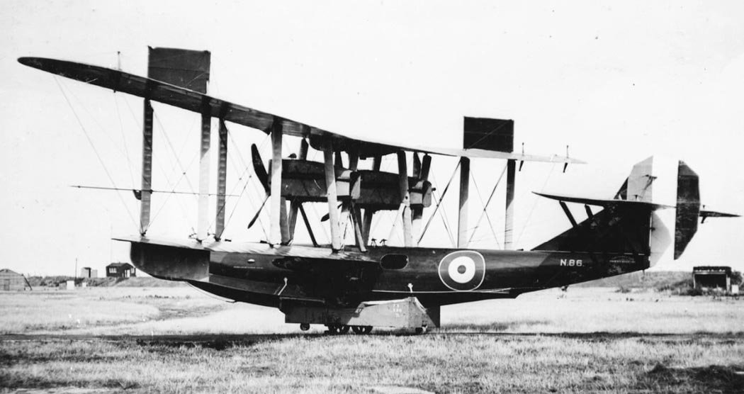
The first flight of N86, named Cork Mk I, took place on Sunday, August 4, 1918, between 6:24 and 6:33 am. The crew consisted of pilot Prodger and, representing the Admiralty, observer Lt Cdr Hume and flight engineer Capt Slater. Two more flights were made by 8:00 am. Prodger reported that the performance was very satisfactory. He believed that N86 was slightly nose-heavy and that the rudder was too small, so he did not attempt maximum speed flight. After the trials, N86 was moored overnight to the mud of the estuary foreshore, and the next morning at 5:30 am, it was swept away. Between these and the next test flight, carried out on the evening of August 9, it was found that the N86’s wing fabric was slightly stretched. However, this factor apparently had little effect on the course of the tests, during which, it was reported, “excellent characteristics” were found.
A new, enlarged rudder was installed on N86, with which a full-load flight of 54 minutes was carried out. The trials were witnessed by Majors Maurice Wright and Miley, who, during the flight held the following morning, were assigned as pilot and passenger respectively. This test flight began at 11:08 am after some difficulty in starting the engines and lasted 12 minutes. Due to an engine malfunction, another flight was arranged during the day, but the engine starting process again proved lengthy. When N86 reached planing speed, it struck a rock and began to sink; the landing ultimately took place, but the aircraft was half full of water. The crew worked to restart the engines, which had stalled shortly after the accident. They succeeded and were able to taxi the flying boat to shore and beach it in the mud. By this time, it was already 7:30 pm.
Rescue operations could not be carried out the next day, as the Phoenix-built F.3 N4416 flying boat was launched and sent for flight tests, leaving no time to escort N86. However, the next morning the hull was repaired, and the aircraft was pulled ashore. After repairs, N86 was flown on August 24, 1918, by Major Wright from the Marine Aircraft Experimental Station located at the Isle of Grain. N86 underwent final inspection at the Isle of Grain the next day and over the following week was flight-tested to obtain preliminary handling, climb, and speed data, which were officially reported in NM 219 dated August 31, 1918. Among the design defects noted in the report was the lack of rigidity of the wing covering. Criticisms were made regarding the cockpit layout: the crew positions, instruments, and throttle control, which was deemed not as good as a pair of separate levers. However, the criticism proved unfounded, as shortly after the hulls were delivered to Bradford, mock-ups of the cockpits were made there using one of the hulls, and their layout was officially approved. Further, the report stated:
“The machine is light to lateral control and, as far as can be seen, the control is sufficient. It comes out of a bank quite easily. The rudder might be a little larger, with a little more balance and a larger operating gear. The elevator is quite light and effective. The machine is a little nose-heavy. The boat is very stable on take-off and landing, no porpoising tendencies were noticed. During taxiing, a fair amount of water is thrown onto the propellers, and the bombs are washed by water thrown up by the keel (the outer surface of the front part of the planing bottom), but not by a solid wave… The machine took off and landed with little clumsiness. Except for spray on the propellers, the exit from the water was very good, and the landing was very soft and free from bumps.”
An investigation into the cause of the wing’s lack of rigidity showed that an unsuitable type of aircraft dope had been used. Since N87 was then under construction, its wings were treated with various dopes, and it was decided to use them to replace N86’s wings. The replacement was carried out in October 1918, and the original wings were sent back to Bradford for re-doping and installation on N87. From preliminary trials, it was evident that N86’s wings were installed too low relative to the hull. Most likely, this fact led to the installation of N87’s wings on the upper part of the hull (the holes in the hull for the spars were plugged). N86’s trials resumed in October after a new set of wings was installed on the aircraft. On October 17, the protocol of trials conducted at Isle of Grain, NM 219B, was published, providing a comparison of N86 and the Felixstowe F.5 prototype N90. The report’s author possibly mentioned that the P.5 surpassed the F.5 in performance characteristics: speed, rate of climb, range, and could carry a larger payload. The report also noted that the P.5 had not yet been tested in rough seas and that the main step had been damaged once. Overload tests were conducted, the results of which were given in report NM 240b, dated May 10, 1920. N86 was later fitted with navigation lights. Subsequently, N86 was used for experiments at Isle of Grain and is known to have flown until late 1924 when it became the subject of impact load tests described in R & M No.926.
Variants and Legacy
Production and assembly of N87, which became known as Cork Mk II, began in late August 1918. On September 24, Phoenix was notified by the Technical Department of the necessity for major changes to the hull. These changes were made according to Air Ministry drawing No.D.S.3.034, carried out by May, Harden & May shipbuilders between October 15 and November 2. The resulting hull resembled the N86 fuselage but had a rear step further aft. From this point, assembly of N87 proceeded steadily, although a further delay occurred when it was discovered that the wrong type of aircraft dope had been supplied and used for covering the wings. Ultimately, on February 21, 1919, the Cork Mk II was sent by road to Brough for final assembly.
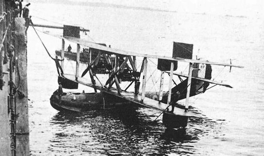
N87’s first flight took place on Friday, March 28, in the afternoon, and being shortened due to strong wind, lasted only 7 minutes. The crew consisted of pilots Majors Wright and Miley, as well as C.P.O. Dryden, Shanate of Rolls-Royce, West of Phoenix, and engineer Edwards. Storms and heavy seas thwarted attempts to bring N87 ashore, damaging a tailplane bracing tube, and it remained moored to a buoy until the following Sunday evening, when it was found that the boat was not submerged. It was noted that the Cork weathered storms well, a fact widely used by Phoenix, comparing N87 to its namesake. Despite the bad weather conditions, the trials were successful: takeoff occurred automatically, handling and stability were excellent. However, criticism was voiced regarding the petrol pumps and valves. Recommendations were made regarding servicing. Test flights were performed again, interrupted by another wing re-doping, for which Phoenix received a contract dated May 24, 1919. In June, N87 was flown by Major Wright at the Isle of Grain, and from then on, the aircraft was used for experiments.
In December 1919, N87’s planing bottom was severely damaged when the aircraft was brought ashore in bad weather on its launching trolley. Repairs were started and completed in early 1920. One result of this accident was the invention of a trolley that used fabric tanks filled with water as an elastic cushion for the hull. In the summer of 1922, a decision was made to install two 450 hp Napier Lion engines on N87. A trial assembly and installation of the engines on modified mounts were carried out in Bradford, then delivered to the Isle of Grain and installed on N87, which was then renamed Cork Mk III. On August 2, 1922, N87’s first flight with the new engines took place; it lasted 10 minutes and was performed under the control of Flt Lt G.E. Livock.
On this day, N87 was scheduled to join an experimental flying boat flight at the start of its journey from Isle of Grain to the Scilly Isles. N87’s flight was delayed due to a fuel system malfunction. Flt Lt G.E. Livock recalled: “We had a ‘do-it-yourself’ system created, I think, not by the company designers, but at Isle of Grain. When you turned on the petrol supply, fuel started going not into the engines, but into the hull. Before the flight, we had to pump out some fuel and clean [the hose].” On August 4, N87 joined the experimental flight from Spithead.
The main objective of the flight was to gain experience operating flying boats away from their home stations, using ships as a base. The unit consisted of a Short N.3 Cromarty (N120), one standard Felixstowe F.5 (N4038), one F.5 with Lion engines (N4839), and N87, accompanied by HMS Ark Royal, the tender HMS Tintagel, a destroyer, and an RAF floating dock, towed by the tug HMS St Martin. The experimental flight was commanded by Sqn Ldr R.B. Maycock. On October 31, 1922, Sqn Ldr R.B. Maycock submitted a final report and recommendations on flight training to the head of the Marine & Armament Experimental Establishment, Isle of Grain. The report provided more detailed assessments of the performance of each flying boat and the rest of the unit. A comparison of aircraft types was made, and it was concluded that N87 was better than the Short N.3 Cromarty and far superior to any F.5. The conclusions took into account the condition of each machine at the start of the flight, and N87 was rated as being in the worst condition!
Attached to the report were pilots’ comments regarding the characteristics and defects of their machines. Flt Lt Livock noted that take-off in calm air with full load averaged 24 seconds, top speed was around 101-104 mph (162-167 km/h), and best cruising speed about 78 mph (125 km/h). Air handling was excellent, except aileron control was slightly insufficient at very low speeds. Rudder and elevator control were very good. Control on water was very manageable at low speeds and good at high speeds, though wingtip immersion was a danger. The machine was very clean during taxiing and less noisy than the F.5. Its seaworthiness was well tested in six gales, which it endured without damage, even without the rear side doors in place. However, Livock observed a noticeable deterioration in performance and handling by the end of the flight, attributing it to a waterlogged hull, significant leaks, and slackening of old, rotten fabric. In summary, the P.5, with minor changes, was deemed infinitely superior to the F.5.
Later, Group Captain Livock recounted the last days of N87: its final flight from Portland on September 18, 1922, was unpleasant due to water in the step compartment and a broken exhaust manifold, forcing an emergency landing. After temporary repairs, rough seas made takeoff unfeasible. It was taxied to Newhaven harbour and moored, but a storm caused it to crash into the pier. Attempts to dismantle it in the water failed as it listed and sank. It was eventually salvaged in pieces and sent back to Isle of Grain.
Interest in the Cork was shown in many circles, particularly by the American aviation mission in August 1918 and by Boulton & Paul Ltd, which received hull drawings for training. Phoenix Dynamo Co considered a civilian variant of the Cork, designated P.8, intended to carry ten passengers or equivalent cargo. Manning also explored the possibility of participating in the “Daily Mail” proposed first non-stop transatlantic flight, with his calculations showing the Cork could easily accomplish it. A further development of the Cork was the English Electric P.5 Kingston flying boat, equipped with Napier Lion engines.
Technical Specifications
| Modification | Cork Mk.I |
| Wingspan, m | 26.06 |
| Aircraft length, m | 14.81 |
| Aircraft height, m | 6.10 |
| Wing area, m2 | 120.03 |
| Empty weight | 3334 |
| Maximum takeoff weight | 5262 |
| Engine type | 2 Rolls-Royce Eagle VIII Piston engines |
| Power, hp | 2 x 360 |
| Maximum speed, km/h | 169 |
| Cruising speed, km/h | 135 |
| Flight endurance, h | 8 |
| Rate of climb, m/min | 152 |
| Service ceiling, m | 3962 |
| Crew | 3 crew |
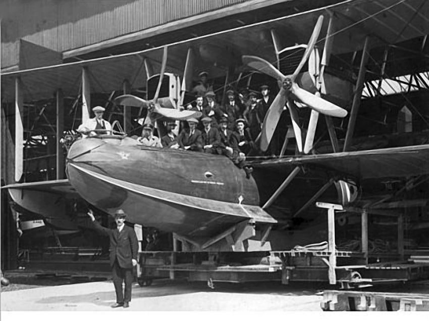
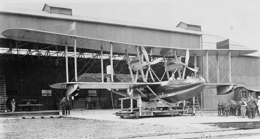
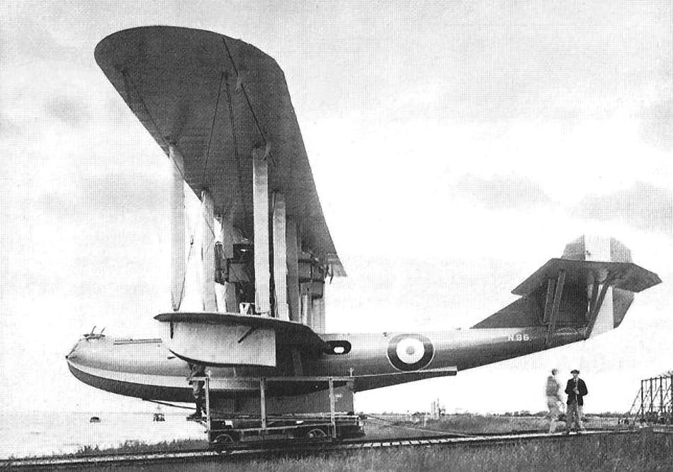
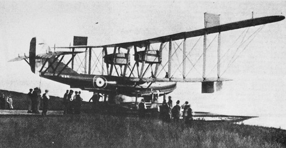
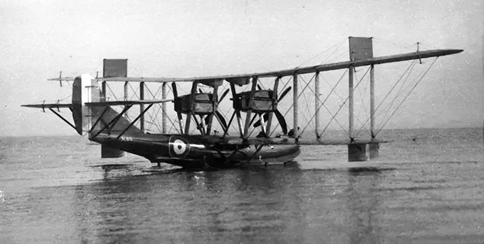
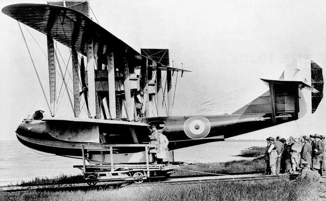
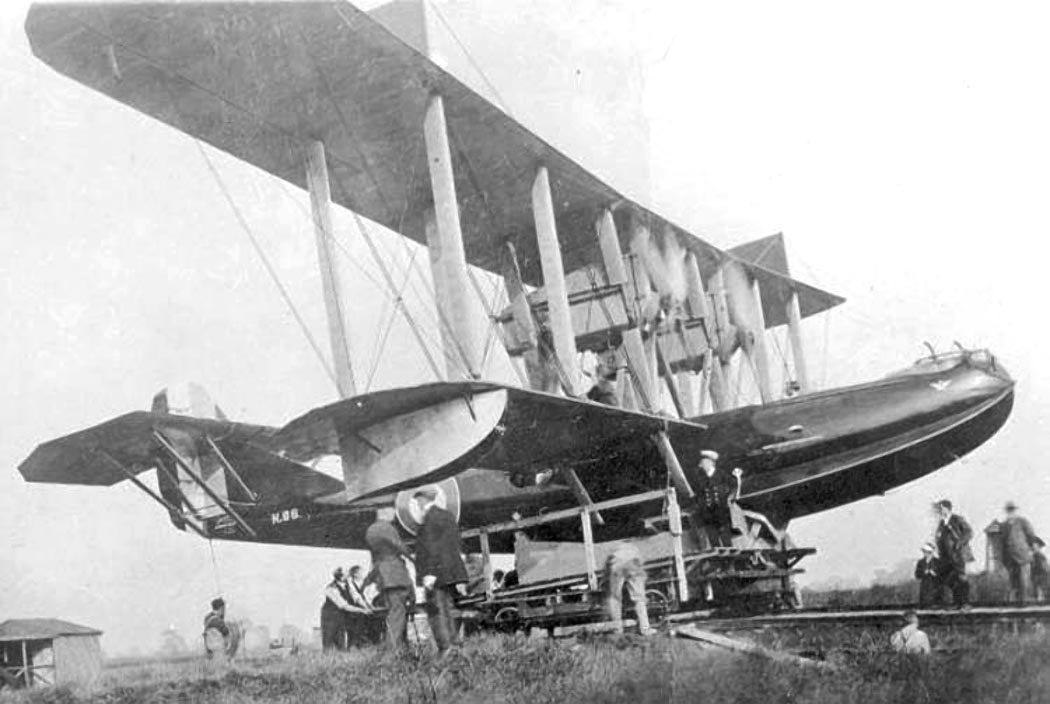
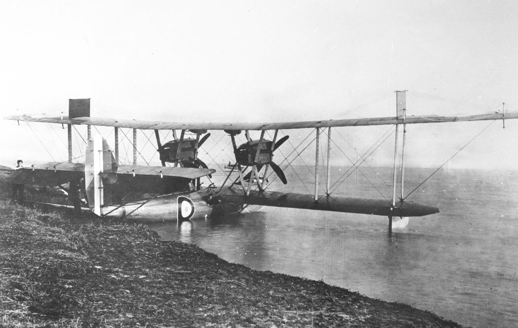
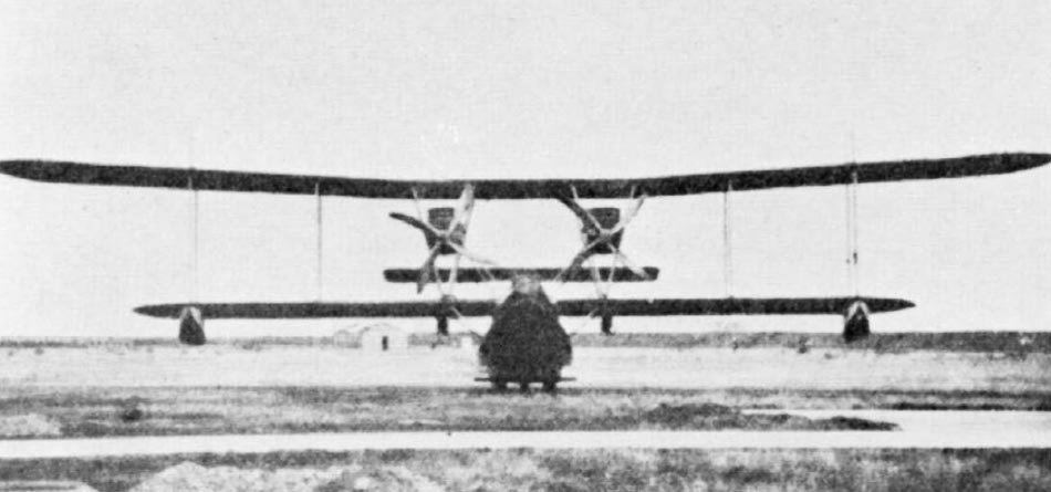
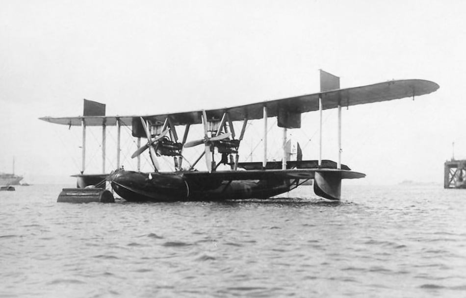
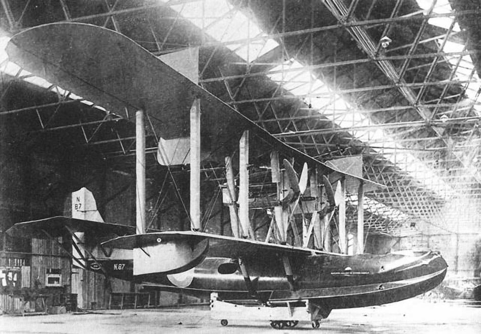
Image gallery of the Phoenix P.5 Cork