Beardmore WB.XXVI Wombat
The May 1985 issue of “The Aeroplane” magazine published the story of the ultralight monoplane Beardmore WB.XXIV WeeBee. Its designer, W. S. “Bill” Shackleton, became the chief designer of the newly opened aviation department of William Beardmore & Co Ltd – a Clydeside shipbuilding company – in early 1924. The Wee Bee was his first project for his new employer.
The civilian aircraft market was extremely small, and it was clear that the company needed to compete for military aircraft contracts. Therefore, Shackleton had to turn his attention to this area. As he had no prior experience in this field, Ogilvie and Partners – a company founded by aviation pioneer Alec Ogilvie that provided consulting services to aviation engineers – was called upon to evaluate his designs.
Initial Design and Expert Feedback
In late May 1924, Ogilvie reported on the proposed two-seater fighter project, which could be fitted with a low-power engine for use as an advanced training aircraft. It seems reasonable to assume that the project, designated WB.XXV, was based on the Wee Bee. Unfortunately, drawings of this design have not survived, but in several respects, it was unconventional.
It was a biplane whose wings had a very high aspect ratio and a thick profile, creating significant lift. The pilot’s cockpit was located far forward in the fuselage, ahead of the wing, which in turn was shifted forward to correctly position the center of gravity and the point of lift application. The main fuel tanks, with a total capacity of 70 gallons (318 litres), were located on the upper surface of the top wing.
A 450 hp Napier Lion engine was installed in the nose of the aircraft directly in front of the pilot; the gunner/observer’s cockpit was located behind the wing. The fuselage was described as “very attractive,” and the pilot’s view as “magnificent.” The tailplane was positioned low relative to the fuselage, while the fin and rudder, which had a long balance portion, were placed on the upper part of the fuselage. The undercarriage consisted of a pair of main struts located forward of the center of gravity and a tail skid. Ground clearance between the lower wing and the wheels was very small. When parked, the aircraft’s fuselage was at an angle of 14½°.
Consultants criticized several aspects of the design, the most important being the distance between the pilot and the gunner. It was noted that they should be positioned as close as possible for the best use of armament and that the only satisfactory layout was to place the pilot behind the trailing edge of the wing with the gunner directly behind him. This crew placement was also preferred for a training aircraft. Shifting the wings forward could also be done in this configuration. The large height of the fuselage was necessary to accommodate the gunner’s cockpit, which had to be deep enough and allow its occupant to stand during maneuvers. The low tailplane was within the gunner’s field of fire.
It was also noted that a large landing angle of the fuselage would obstruct the pilot’s forward view during takeoff and landing, and that difficulties would be emphasized by the far-forward placement of the main landing gear struts, which would create a large load on the tail skid and require significant strength in the rear fuselage. It was believed that the proximity of the wheels and the lower wing created a risk of damage to the latter during taxiing over rough terrain. It was noted that the high engine power would likely cause a strong torque, leading to yawing of the fin and rudder, which were entirely located on the upper part of the fuselage. It was also suggested that directional balance would be better if the fin were located partially above and partially below the fuselage with a horizontally [likely vertically] placed rudder. The balancing part of the fin was too long and prone to flutter.
Despite the good gap-to-chord ratio, it was believed that using a thick wing profile in a biplane could lead to a serious loss of efficiency. Conversely, while a high wing aspect ratio was good for efficiency, it was unsuitable for combat aircraft that required rapid lateral control. It was thought that the wing area was excessively large and that the wingspan could be reduced. Such a reduction “would also have the advantage of reducing the rather long cantilevered wing sections.”
Relocating the fuel tanks from the upper wing was advised to allow for fuel dumping during an emergency landing. Although the calculated performance for a trainer aircraft was satisfactory, for a fighter it was insufficient. A wing loading of 9.04 lb/ft² (44.14 kg/m²) provided a sufficiently low landing speed, but it was recommended to recalculate performance based on a wing loading of at least 12 lb/ft² (58.6 kg/m²), which would also significantly save wing structure weight. Fuel was only sufficient for 2½ hours of flight, which was considered insufficient; also, the weight of necessary military equipment (excluding armament) had not been calculated.
From Ogilvie’s report, it became clear that significant upgrades were required. Whether changes were made, or the old project was abandoned and a new one developed, remains a mystery. In 1924, Beardmore built the icebreaker “Krisjanis Valdemars” for the Latvian government, and it seems possible that during negotiations with the Latvians, the company, on its own initiative, made a proposal for a new fighter design. The Latvians took the bait and ordered the aircraft, designated WB.XXVI, which was still in the design stage, as it was necessary to ensure minimum interference in the gunner’s field of fire. At this stage, the fuel tanks were located on the upper surface of the top wing, and consultants again recommended placing the tanks below or within the wings. The Air Ministry considered the placement of tanks on the upper wing as “extremely undesirable” (a noticeable change since the Fairey Fawn).
It was noted that the Eagle engine variant would weigh 350 pounds (159 kg) more than the aircraft equipped with a Jaguar engine. The latter was considered to have significant advantages in terms of performance and overall suitability. Since the aircraft was to be operated in a cold climate by “moderately trained personnel,” such a decision seemed wise and allowed avoiding many of the problems inherent in water-cooled engines.
A new type of main landing gear struts was proposed, however, it was considered unreasonable to install them on a fighter intended for a foreign government whose country had relatively low technical capabilities. A more conventional landing gear was recommended, especially since the new type of undercarriage might have required significant research and development work. In the February 26, 1925 issue of “Flight” magazine, it was stated that “a government on the Continent” had ordered a batch of two-seater military biplanes from Beardmore. At this stage, no photographs or drawings were published, and readers had to be content with a brief description.
Innovative Engineering and Armament
In late 1924 – early 1925, the Royal Aircraft Establishment (RAE) at Farnborough, acting under Air Ministry instructions received in a letter dated October 27, 1924, conducted wind tunnel tests on a 1/10 scale wooden model of the WB.XXVI submitted by Beardmore. During the tests, lift, drag, and pitching moments were measured; the effect of a wing-mounted radiator was also investigated. These tests pursued another goal: to determine whether the hinged attachment of the front part of the tailplane would provide sufficiently powerful pitch control to make changes in the angle of attack of the entire tailplane unnecessary. Pitching moments were measured with a rotation about the axis up and down by 10°, and it turned out that this was equivalent to moving the entire tailplane up or down by only about ½°. The report concluded that the control was “extremely ineffective.”
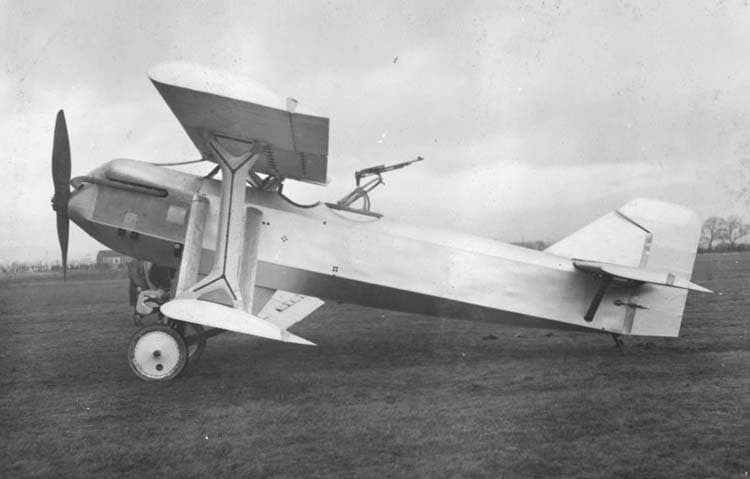
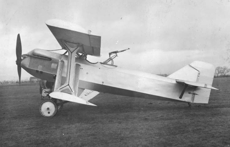
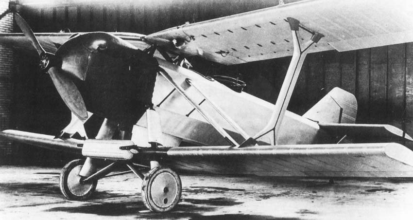
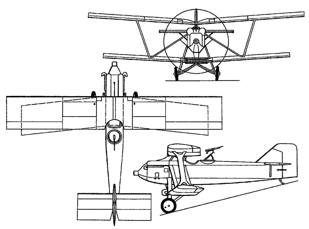
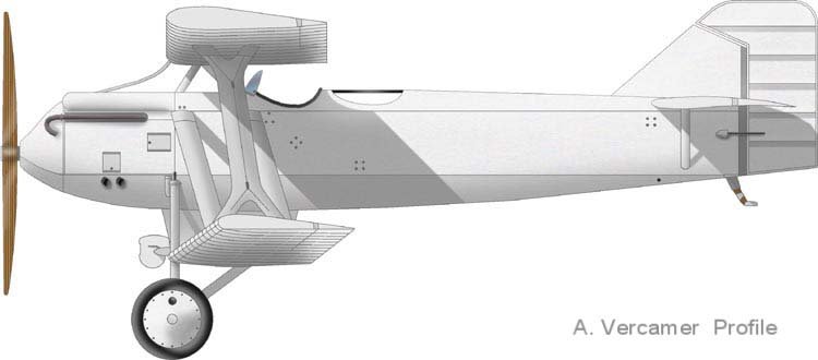
The first full description of the WB.XXVI appeared in August 1925, when the aircraft was said to be “nearing completion,” and even then, only a general arrangement drawing and photographs of the wind tunnel model were shown. It was not until December that photographs of the assembled aircraft were presented. Bill Shackleton undoubtedly created an unusual (and angular) design. Described as the first “large” aeroplane designed by Shackleton after starting work for Beardmore, the aircraft was conceived as a high-performance two-seater fighter.
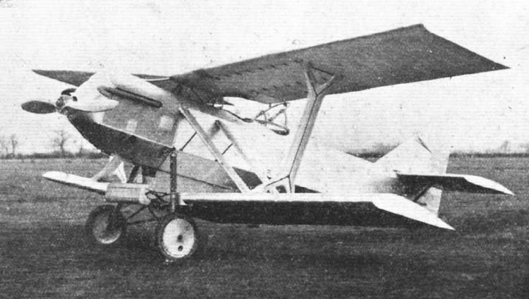
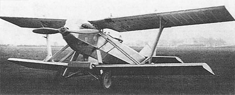
Despite the biplane layout being chosen for greater structural rigidity and low weight combined with a better field of view, Shackleton aimed to approach monoplane aerodynamic efficiency by foregoing interplane bracing and introducing a large gap-to-chord ratio. The fuselage structure, which had flat sides in cross-section, consisted of spruce longerons with frames made of spruce and three-ply plywood. The airframe was covered with three-ply birch plywood and fabric, then the skin was painted and varnished for waterproofing. Immediately after construction, no fitting was required, thus minimizing the need for in-service maintenance. The lower wing was connected to the fuselage by means of a streamlined “keel,” manufactured as a single unit with the fuselage frame and attached to the center section of the lower wing.
Forward of the fire bulkhead in the front of the fuselage, everything was made of steel, including the simple and rigid engine mount, designed for quick removal of the entire power plant. The 360 hp Rolls-Royce Eagle IX engine, housed in a close-fitting cowling, had short exhaust pipes extending forward and then curving back. With the help of a special Lamblin radiator, installed in the leading edge of the lower center section, the aircraft’s nose was given a more streamlined shape.
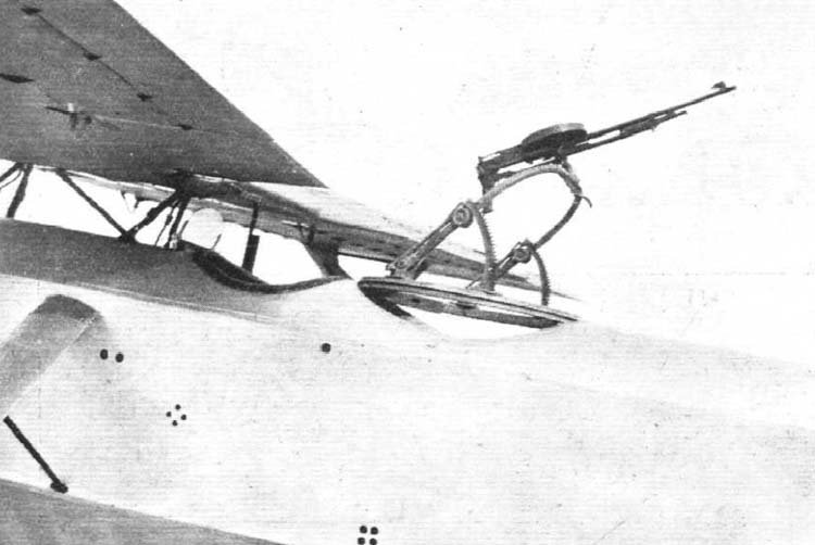
To ensure close interaction between the pilot and gunner, their cockpits were located very close to each other. The pilot was positioned directly beneath a semicircular cutout in the trailing edge of the upper wing. The wing itself became thinner at this point, thereby creating as little drag as possible. In the front of the aircraft, “latest” 0.303″ (7.7 mm) Beardmore-Farquhar machine guns were installed, firing forward through the propeller disc using a Constantinesco synchronizer; in the gunner’s cockpit, one or two machine guns were placed on a Scarff ring mount. Ammunition for the gunner’s machine guns was housed in a thin-section installation with seven circular rotating trays. The installation itself was mounted above the top of the armament. At this time, it was unusual to have front and rear machine guns of the same type – normal practice was to install Vickers machine guns for forward firing and Lewis machine guns on the Scarff mount for rear firing. The advantages of operational compatibility were obvious. Invented by Colonel Moubrey G. Farquhar of Birmingham, the machine gun was one of the lightest ever made, weighing, with ammunition, 16.25 pounds (7.371 kg).
Thanks to its location, the gunner could fire his weapon over almost the entire upper hemisphere and almost vertically downwards, with a fuselage-related vertical blind spot of approximately 10°. Since the vertical fin was cantilevered without external bracing, and the tailplane on each side was reinforced by single lower struts, they created minimal obstruction to the gunner’s field of fire. His cockpit was spacious: in cross-section, the fuselage had a height of 3 feet (0.914 m) and a width of 4 feet 1½ inches (1.257 m).
The fin itself was large. It was angular in shape and carried an equally angular, fabric-covered rudder with a large horn balance. The two-spar rectangular tailplane had a constant chord length, and the elevators were fabric-covered and unbalanced. Due to the difficulties of installing a conventional controllable tailplane of cantilever or semi-cantilever design, Shackleton developed a cockpit-controlled pivoting leading edge, which created the effect of positive or negative camber instead of the usual positive or negative angle of attack. It was stated that this device allowed for neutral trim or a “feel” on the control stick at all flight speeds.
The upper and lower wings had identical construction, consisting of spruce spars and ribs made of spruce and three-ply plywood. The entire wing, from the leading edge to the rear spar, had plywood sheeting, which provided great structural strength and resistance to torsional loads. To increase resistance to tangential stresses, the fabric covering was attached to the wing at an angle of 45° to the leading edge (a practice applied since the Wright brothers). The ailerons, which had a constant chord length, were fabric-covered and hinged to the rear spars of the upper and lower wings; the ailerons were controlled by direct-acting rods and cables or tubular torsion bars, pulleys were not used. The mechanism was entirely housed within the wings, where sliding doors were provided for adjustment and inspection.
While the upper wing, with a span of 37 feet (11.28 m) and a chord of 5 feet 6 inches (1.68 m), was straight and plank-like, the lower wing, with a span of 32 feet (9.75 m) and a chord of 5 feet (1.52 m), featured tips with a sweep of 5.8°. The upper wing, consisting of two panels joined at the centerline, housed four fuel tanks: one in each panel forward of the front spar and one behind the rear spar, not extending beyond the inner edges of the ailerons. The tanks’ placement was profiled to follow the curvature of the wing’s profile, which had a large chord and high lift properties. The tanks had a capacity of 75 gallons (341 l) of fuel, which fed by gravity to the carburetor.
The bracing system consisted of cabane struts running from the upper parts of the fuselage longerons to the root sections of the upper wing; wide interplane I-struts, forked at the upper and lower parts connecting to the wings; two compression struts (one on each side) running from the upper fuselage longerons to the lower wing longerons. The I-struts, which had a streamlined cross-section, were made of duralumin plates, while the compression struts were made of steel tubes covered with duralumin fairings. Short auxiliary struts, extending from the lower wing longerons, supported the compression struts at a small distance from the fuselage. The struts were attached to the fuselage by hinged joints, allowing for quick installation and removal of the wings. After the machine was adjusted, no further corrections were needed and the wings were rigidly fixed in position using bolts and pins. During assembly, the correct angle of attack was obtained by adjusting the attachment of the I-struts to the upper and rear lower wing longerons. The absence of bracing wires significantly simplified field maintenance.
Another distinctive feature of the WB.XXVI was its main landing gear struts, which were jointly patented by Beardmore and Shackleton. The struts were of all-metal construction and contained no rubber or other perishable materials. Impacts during landings and taxiing were absorbed by a compression system of chrome-vanadium steel coil springs; impacts were quickly damped by Ferodo friction pads, preventing the aircraft from bouncing. Streamlined telescopic front supports were attached to the lower fuselage longerons and passed through the leading edge of the lower wing, while curved axles and rear supports were attached to the under-fuselage vertical fin at the attachment points of the lower wing longerons. The struts and axles were provided with fairings. Together with the wheels, tires, and fairings, the assembled landing gear comprised just over 4% of the aircraft’s total flying weight, yet its working travel remained 9½” (0.241 m); the weight of the main struts compared favorably with other types of landing gear with similar travel. An all-metal tail skid with steel springs was fitted with an easily replaceable shoe.
Flight Performance and Ultimate Fate
By this time, the alternative Jaguar power plant was inferior to the 450 hp Napier Lion engine, and it was stated that the latter would be installed on the WB.XXVI and that “the performance is adequate to that currently possessed by any aircraft of a similar type built in any country.”
It proved impossible to ascertain the date of the WB.XXVI’s first flight, but the December 31, 1925 issue of “Flight” magazine stated that it had been completed “some time ago” and that during flight trials, the aircraft “approached its calculated performance values.” These tests were conducted by Beardmore’s chief test pilot, Captain Archibald Norman Kingwill. In a 1970 interview with the author, Kingwill recalled that the aircraft initially had a pressure fuel tank installed between the cylinder blocks. The aircraft never flew in this form because the design was changed due to Rolls-Royce’s safety complaints. Kingwill also said that Shackleton gave the aircraft the designation WB.XXVI “Wombat.”
In mid-to-late February 1926, enthusiastic reports on the WB.XXVI’s performance appeared in the aviation press. “The Aeroplane” magazine stated that the results of its “official tests” were “almost sensational.” During its speed, climb, and altitude trials, the aircraft showed a maximum-to-landing speed ratio of 3 to 1. Kingwill then dived the aircraft at 200 mph (322 km/h), and immediately after recovery from the dive and subsequent leveling, the machine showed no structural integrity deficiencies. After demonstrating the “falling leaf” maneuver, Kingwill performed rolls and axial rotations (spins) with the machine, after which, at high speed, he put the aircraft into a turn whose bank angle approached vertical. Then followed what was considered the most important demonstration of all. Maintaining the aircraft in horizontal flight, he cut the engine, and when the stall angle was reached, the throttle was closed, and the control stick was pulled back. The aircraft reached an angle of 60° to the horizontal and began to settle on an even keel. To show that the machine was fully under control in this fully stalled state, Kingwill rocked it from side to side and pitched it forward and backward.
Then, with the engine at full power, Kingwill flew horizontally for approximately 1000 feet (305 m), after which he began to climb almost vertically until the aircraft stopped and began to fall tail-first. The aircraft, with the engine at full power, simply dropped its nose a few feet and began to settle. The fuselage pitch angle to the horizontal again became 60°, and again it was shown that the machine was fully controllable. Since the WB.XXVI had no special lateral control devices, this display was exceptional. Considering that most aircraft entered a spin and dive after stalling, in the case of the WB.XXVI, a loss of speed was, as “The Aeroplane” wrote, a “safe and usable maneuver.”
“This achievement,” wrote “Flight,” “is among those that any designer… can be proud of.” It was also reported that the machine had withstood numerous tests to determine the range of movement in the landing gear struts and that the greatest deflections were recorded during high-speed taxiing (over 50 mph [80 km/h]) over very rough terrain. Oddly enough, in deliberately hard landings on the same surface, the amplitudes were not as great. The landing gear withstood rough handling without problems. However, it should be borne in mind that press reports were based on data provided by Beardmore.
In fact, although the WB.XXVI apparently did possess exceptionally good low-speed handling characteristics, this was not enough. In recent years, H. J. Steiger, who worked at Beardmore at the time, said that the machine was too heavy and too slow; Shackleton stated his desire for a Napier Lion engine, and Kingwill, in turn, recalled that the Latvians were not prepared to pay for a more powerful engine. Kingwill also said that the machine was good for aerobatics, and that he later used this aircraft with “monotonous regularity” in what later became known as “Derry turns.” Due to the installation of the upper wing and the low placement of the lower wing, the pilot’s view was “excellent.” He recalled that the WB.XXVI’s ailerons were too heavy, but there were no problems with the landing gear, although it was “a bit stiff.”
Shackleton recalled that during Kingwill’s flights, he was quite concerned about the terminal dive speed with a loop at the bottom. He also said that the aircraft was plagued with propeller problems and that they never had a suitable propeller. There were also problems with the Lamblin radiator, which in one instance boiled over. This was confirmed by G. Randall, who was an inspector for the WB.XXVI and participated in test flights with Captain Kingwill. Randall wrote: “The engine was used to boil water, vigorously directing it 4 feet (1.22 m) below the engine’s outlet pipe… Maximum speed was about 145 mph (233 km/h), and only one thing this aircraft did wonderfully was the falling leaf, with its heavy I-struts and flat wingtips. With the nose only pointing down, you can move the stick sideways and forward, and the aircraft will be effective.” Randall described the WB.XXVI as a “failure.”
Despite the poor results, plans to export the WB.XXVI to Latvia developed. On April 15, 1926, Flt Lt G.S. Oddie (later Air Cdre Oddie DFC AFC) of the RAE flew the aircraft for its Certificate of Airworthiness (C of A) and performed three flights lasting 15, 40, and 20 minutes. In 1971, in a letter to the author, he wrote: “Although the Latvian fighter was quite serviceable, I well remember my words to my wife when we discussed this flight. I said, ‘Yes, I will gladly issue it a certificate of airworthiness – for it is going to Latvia, not to our Air Force.’ I spoke thus because of its handling: it was sufficient for the aircraft to be flown, but personally, I would wish for something quite different from a fighter. It very much resembled [in its air behaviour] the two-seater Fairey fighters supplied to the Royal Naval Air Service.”
Oddie noted that his task was only to assess the aircraft’s airworthiness, and the company was keen for comments to be strictly limited to that factor. In later stages at Renfrew, the WB.XXVI’s single exhaust pipes on each side were replaced by separate outlets for each cylinder. On May 14, 1926, following Oddie’s test flights, Beardmore was issued Certificate of Airworthiness No. 981 for the WB.XXVI. The internal company number specified in the C of A was WB.11/1, while in the company’s reporting documents, the factory number AV.3 was assigned. The contract cost £3500, and by December 1925, £7357 had been spent on design.
Soon after, the WB.XXVI was sent to Latvia, where Captain Kingwill tested and demonstrated it in flight over Spilve airfield, near Riga. Latvian aircraft designer Kārlis Irbītis claimed that the machine flew only three times in Latvia. The last flight was performed under the control of Lieutenant Aleksandrs Zariņš (later chief test pilot of the VEF company’s aviation department), who told Irbītis that the engine apparently overheated and seized in flight, but he managed to make a successful emergency landing.
The commission leaders appointed to approve the aircraft were not satisfied with its characteristics, and it was rejected. It is known that Bert Hinkler’s flight on August 27, 1927, from Croydon to Riga in an Avro Avian prototype (civil registration G-EBOV) – the longest non-stop flight in a light aeroplane – was made to conclude some business on behalf of Beardmore. This was likely related to the cancellation of the WB.XXVI contract. Possibly until the end of 1935, the WB.XXVI languished at Spilve in a hangar belonging to the Latvian aviation regiment. Then the Latvian government sent the aircraft back to the manufacturer, who presumably scrapped it, as records of the machine disappear.
Although Beardmore advertised the WB.XXVI in the aviation press throughout 1926, there were no other buyers. The advertisements played on the machine’s handling characteristics in stall, but it can be assumed that potential buyers would have been more interested if the company could have boasted exceptionally high performance. Perhaps with a suitable engine, it might have achieved this, but this option remains in the realm of speculation.
Technical Specifications
| Modification | WB.XXVI |
| Wingspan, m | 11.28 |
| Length, m | 8.50 |
| Wing area, m2 | 33.10 |
| Empty weight | 1162 |
| Normal takeoff weight | 1809 |
| Engine type | 1 Rolls-Royce Eagle IX Piston engine |
| Power, hp | 1 x 360 |
| Maximum speed, km/h | 233 |
| Cruising speed, km/h | 195 |
| Flight endurance, h.min | 2.30 |
| Service ceiling, m | 6100 |
| Crew | 2 crew |
| Armament | Two synchronized 7.7-mm Beardmore-Farquhar machine guns and one or two identical machine guns on a turret in front of the cockpit. |
Image and diagram gallery of the Beardmore WB.XXVI Wombat
 WB.XXVI |
 WB.XXVI |
 WB.XXVI |
 WB.XXVI |
 WB.XXVI |
 WB.XXVI |
 WB.XXVI |
ArchivoAéreo Editorial Team
A group of aviation researchers and enthusiasts dedicated to documenting and preserving global aeronautical history. All articles are reviewed to ensure historical accuracy.
Sources & Accuracy
The information presented in this technical sheet has been compiled from declassified flight manuals, historical archives, and specialized literature. While we strive for maximum accuracy, some performance data may vary depending on the specific variant or operational conditions.