Boeing YC-14
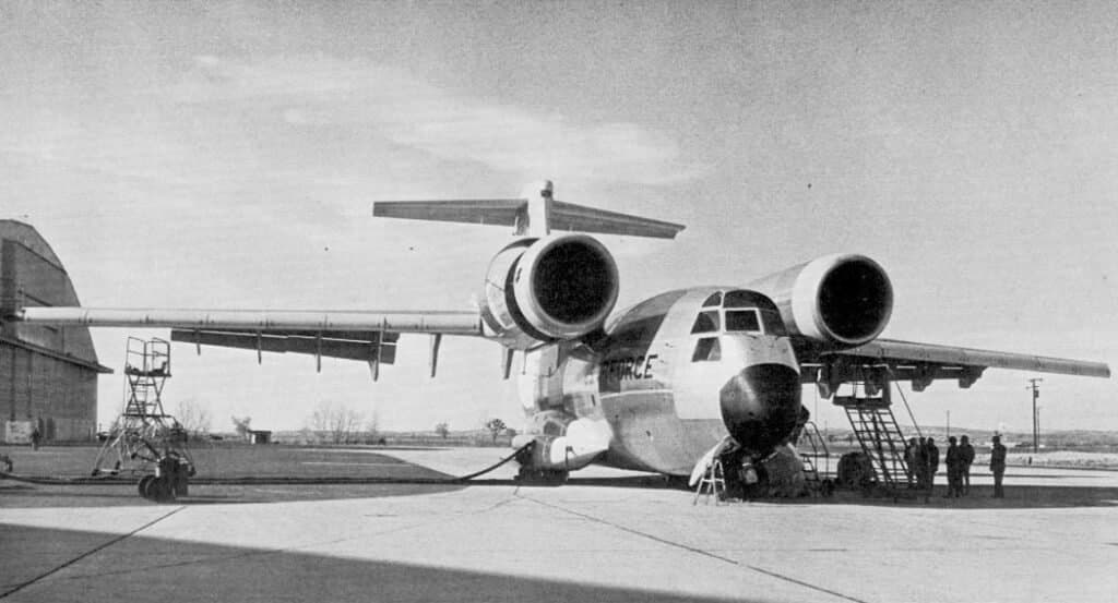
The first attempt to replace the military transport “Hercules,” widely used not only in the USA but in many countries, was the creation of the short takeoff and landing (STOL) aircraft YC-14 and YC-15 under the AMST program.
One of them, chosen after a competition, was intended to provide US tactical armed forces with efficiency characteristic of civil transport aviation, driven by the shift from turboprop (TPD) to turbofan (TRDD) engines. Although both aircraft remained experimental, the YC-14 is of particular interest to us because the STOL aircraft concept embedded in it was fully adopted by Ukrainian aircraft manufacturers in the An-72/74. The YC-14 was designed for operation from rudimentarily prepared short runways and was intended to perform tasks beyond the capabilities of the aging C-130.
In January 1972, requests for proposals for the new aircraft were sent to nine American firms. The general requirements for the aircraft under the AMST program included, in particular, the need for its use in combat zones. This, in turn, required good handling characteristics at low flight speeds, high productivity, and a relatively low aircraft cost, which was linked to structural simplicity.
For cost reasons, a straight, jointless wing was chosen for the YC-14. By abandoning the use of sweep, a traditional method for achieving high cruise speeds, designers were forced to thoroughly investigate the possibility of using advanced supercritical airfoils to achieve acceptable drag from a thick and, consequently, light wing.
Advanced airfoils, where pressure is distributed more evenly along the chord without a peak at the nose, were already in use on passenger aircraft like the A-300B, Boeing 747, DC-10, and L-1011. Such pressure distribution allows an increase of approximately 110 km/h in the speed at which a sharp increase in drag occurs due to shock wave formation. Similar airfoils were chosen for the YC-14. However, its cruise speed, corresponding to Mach 0.7, was less than that of jet transport aircraft but greater than the Hercules.
When operating the aircraft in STOL modes, the wing’s lift coefficient reaches up to 4.5, and any deviation from the appropriate angle of attack is accompanied by a significant decrease or increase in induced drag. Therefore, during approach, the aircraft had to be controlled by the autopilot with continuous pilot monitoring.
The horizontal stabilizer had a large area to create the necessary control moments at very low speeds, ensuring quick pitch response and nose-wheel lift-off during takeoff. The YC-14 used a two-section elevator to counteract the nose-down moment generated by the high-mounted engines during the takeoff roll.
STOL takeoff with one engine failed is complicated when using a lift augmentation system, due to difficulties with directional control at low speeds. Therefore, the YC-14 was fitted with a very large fin and rudder. The use of a straight wing with panels up to 30m long reduced the machine’s cost and weight.
This was facilitated by the elimination of heavy and expensive joints where the wing met the fuselage, nearly halving the number of parts in these areas, as well as the use of a constant-chord fin and rudder and a simplified fuselage design.
Active Lift Augmentation System
A distinguishing feature of the YC-14 was its active lift augmentation system. The tendency of a jet to “stick” to the surface it flows over and deflect along with it from its original direction had been known for a long time. This phenomenon was first investigated by H. Coandă in France before World War II, though he encountered it in the 1910s. Since then, this effect has been named after him. While Coandă’s efforts were mainly directed at improving ejectors, this effect is used in all boundary layer control systems through blowing.
The first full-scale supercirculation experiments were conducted in 1954. In these, a gas jet with sufficient energy was blown from the wing’s trailing edge, forming a jet flap. NASA’s interest in jet flaps in the late 1950s led to the development of a powerplant in which the entire jet exhaust was released through a relatively thin slot over the wing’s upper surface, creating additional lift.
However, transport aircraft engines of that period did not have sufficient thrust and failed to provide the necessary lift increase. The idea remained without practical application until research conducted at NASA showed that powerful exhaust jets from high-bypass turbofans could be deflected by this method, at large angles and without excessive losses. These and other experiments sparked Boeing’s interest in this lift augmentation method.
The aircraft’s twin-engine layout most fully matched the purpose of the future YC-14. Very high thrust-to-weight ratio, necessary for single-engine takeoff, and acceptable climb rate, combined well with the residual thrust required for cruise flight at speeds corresponding to Mach numbers of 0.7-0.74.
Two powerful General Electric CF6-50D turbofans, each with 23,140 kgf thrust, were installed above the wing, which reduced the likelihood of ingesting foreign objects from the ground. The high placement of the engines and the shielding effect of the wing allowed thrust reversal without creating dust and dirt clouds when landing on unprepared surfaces.
Furthermore, the wing, by shielding the turbofan exhaust jets, reduced aircraft noise levels and made it difficult for infrared-guided missiles to home in. The engines were positioned close to each other to minimize yaw and roll moments in case of an engine failure.
The turbofan exhaust stream flowed over the wing’s upper surface, blowing over the flap, whose deflection changed the engine’s thrust vector. The flaps, with a maximum deflection angle of 70°, consisted of two sections—front and rear—which, when deflected, formed a continuous curved surface. If one engine failed, the front part of the corresponding flap automatically separated, creating slots between the sections, increasing lift, and significantly reducing the roll moment.
On the wing section not exposed to the turbofan’s exhaust flow, conventional double-slotted flaps were used. Interceptors located in front of them served for direct lift control (DLC), creating almost instantaneous changes in the approach glideslope angle. A Krueger flap covered the entire leading edge of the wing, and its effectiveness was enhanced by boundary layer blowing at the wing’s nose using DLC.
Advanced Control Systems
The DLC system was powered by air bled from the turbofans, which flowed through a common manifold between the two engines to prevent lateral asymmetry in case of an engine failure. During takeoff, the DLC system bled air only from the 8th compressor stage, maintaining the necessary thrust reserve for aircraft acceleration and steep climb. For landing, the system operated from both the 8th and 14th stages, with air from these stages mixed in an ejector.
Thrust reversal control was integrated with the DLC system, so activating this device shut off the air bleed valves from the 14th compressor stage to increase engine thrust needed for aircraft braking. Air bled from the engines was also used for the anti-icing system, ensuring the DLC system’s operation in all meteorological conditions. As a result, the YC-14 could take off at 180 km/h and land at 157 km/h.
The most critical case, undoubtedly, was the go-around with one engine failed. For short-field takeoff, the aircraft was designed for a 6-7° approach angle, compared to the traditional 3°40′. This required a significant reserve of lift to overcome inertia and braking during the aircraft’s descent.
As a result of noticeable lift asymmetry, a large roll moment was created, which was countered by the formation of slots on the flap behind the failed engine’s wing panel, partial retraction of the outer flaperon on the opposite panel (for this purpose, double-slotted flaps could deflect differentially), and a slight deflection of the aileron.
For a normal approach, about 30% of the maximum engine thrust was required. If one engine was shut down, the other was set to maximum thrust. Since the engines were located quite close to the aircraft’s axis, the working turbofan could induce significant lift on both wing panels.
In the event of an engine failure during a short takeoff, the autopilot, sensing the loss of thrust, would re-trim the aircraft until the working engine reached maximum power. The engine nacelle protruded in front of the wing. Flows from the gas generator and fan sections combined and exited a common nozzle.
Operational Characteristics & Design
For landing on short runways, the aircraft needed to rapidly change its glideslope angle while maintaining a constant approach speed. Using engine thrust for this purpose, as done on conventional aircraft, was impossible on the YC-14 due to the short maneuvering time in the final phase of flight. Furthermore, changing engine thrust was accompanied by undesirable changes in wing lift and drag, which could be compensated for by the pilot or the automatic control system.
The flap actuation system, with its relatively high deflection speed, ensured precise control of the flight path. The YC-14’s control system had a mode in which any change in engine thrust was accompanied by flap deflection. These variations served to balance, matching the required thrust with the descent trajectory. When the thrust reached the desired value, the flap automatically returned to its normal position and was ready for action during the next change in glideslope angle.
The engine air intake was non-adjustable. It provided a high degree of total pressure recovery and uniform pressure distribution at the engine inlet across all flight regimes and angles of attack. The engine nacelle had low aerodynamic drag in cruise flight. The turbofan nozzle was angled upwards to divert hot exhaust gases from the wing’s upper surface.
Thrust reversal was created by rotating a reflective flap, forming the upper part of the nozzle structure. The flap blocked the nozzle, causing the jet to deflect upwards and forwards. Near the leading edge of the flap, there was a visor that regulated the direction and shape of the reversed flow. The deflection of both the flap and visor was controlled by a single hydraulic actuator.
The semi-elliptical exhaust nozzle was also non-adjustable, apart from a small triangular flap located on the outer side of the nozzle, which could be set in two fixed positions. At low speeds, this flap opened, promoting wider spreading of the exhaust gas flow in a thin layer over the wing surface and the extended flap, thereby achieving better downward deflection of the flow.
On the upper surface of the wing, vortex generators were present to increase the energy of the boundary layer, delaying flow separation on the deflected blown flaps. In cruise mode, these vortex generators were flush with the outer surface of the wing, while at low speeds, they extended into the flow.
The triangular nozzle flap and vortex generators were actuated by hydraulic cylinders depending on the flap position. The nozzle flap opened with flap extension, and the vortex generators remained in the raised position when flap deflection angles exceeded 25°.
From the start of the YC-14 aircraft program, great attention was paid to future maintenance issues. As a result, the aircraft featured good engine access. For example, inspection of the thrust reverser mechanism was performed from the upper surface of the wing, accessible through a hatch in the fuselage ceiling.
The first YC-14 flight took place in October 1976. The following year, a second aircraft joined the tests. On both prototype aircraft, altitude-speed characteristics were determined, the possibility of in-flight engine restarts was investigated, and flutter parameters were studied. During one landing on the second aircraft, the rollout distance was reduced to 150m with a headwind speed of 7.7 m/s, and the minimum approach speed to 126 km/h.
During flights, when maneuvering with less than one g, it was discovered that the Krueger flaps spontaneously extended into the flow at high speeds. The gap that appeared between the wing and the flap worsened the aircraft’s aerodynamics. Consequently, the speed had to be limited to 500 km/h, and on production aircraft, it was planned to replace the flaps with slats.
Test flights included dropping single loads weighing up to 9 tons. During dummy drops, it was found that personnel could only be paradropped through the side doors, as an excessively high turbulence zone formed behind the aircraft when the cargo ramp was open.
In May 1977, the YC-14 was demonstrated at the Le Bourget Airshow, performing a ferry flight from Edwards Air Force Base (California) to Wright-Patterson Air Force Base (Ohio), Goose Bay, Mildenhall (RAF Base, England), and then to Paris.
By this time, military requirements for the aircraft had changed. If a range of 4800 km was previously considered ferry distance, it now needed to carry 17.2 tons of cargo over that distance. The new requirements led to the need to increase the wing area by 20%. Calculations showed that the increase in takeoff weight was compensated by the machine’s increased efficiency. However, for a number of reasons, including funding limitations, neither the military transport aircraft nor its civilian variant with an increased fuselage length reached serial production.
Technical Specifications
| Modification | YC-14 |
| Wingspan, m | 39.32 |
| Aircraft length, m | 40.13 |
| Aircraft height, m | 14.73 |
| Wing area, m2 | 163.69 |
| Empty weight | 53297 |
| Maximum takeoff weight with STOL | 77111 |
| Maximum takeoff weight | 107501 |
| Engine type | 2 General Electric CF6-50D Turbofan engines |
| Thrust, kgf | 2 x 23133 |
| Maximum speed at altitude, km/h | 811 |
| Maximum speed at sea level, km/h | 649 |
| Cruising speed, km/h | 723 |
| Ferry range, km | 4815 |
| Operational radius, km | 740 |
| Maximum rate of climb, m/min | 1935 |
| Service ceiling, m | 13716 |
| Crew, crew members | 3 |
| Payload | 150 paratroopers or 36742 kg of cargo |
Image and diagram gallery of the Boeing YC-14
 C-14 |
 C-14 |
 C-14 |
 C-14 |
 C-14 |
 C-14 |
 C-14 |
 C-14 |
 C-14 |
 C-14 |
 C-14 |
 C-14 |
 C-14 |
 C-14 |
 C-14 |
 C-14 |
 C-14 |
 C-14 |
ArchivoAéreo Editorial Team
A group of aviation researchers and enthusiasts dedicated to documenting and preserving global aeronautical history. All articles are reviewed to ensure historical accuracy.
Sources & Accuracy
The information presented in this technical sheet has been compiled from declassified flight manuals, historical archives, and specialized literature. While we strive for maximum accuracy, some performance data may vary depending on the specific variant or operational conditions.