BRO-11 Glider
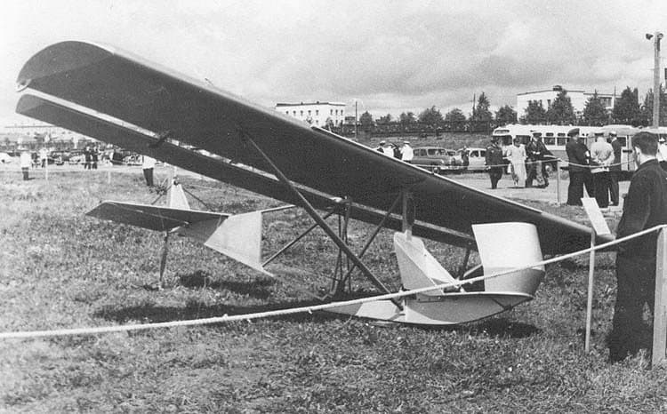
The prototype of the BRO-11 glider was constructed in 1954. Its designer, B. I. Oshkinis, aimed to create a mass-produced glider that was inexpensive, reliable, and simple to manufacture. The vision was for it to be easily built by any glider club, allowing aspiring aviators to undergo theoretical and ground training, and practice short takeoffs and flights from small slopes.
Accepted for serial production in 1955, the BRO-11 was widely used in DOSAAF clubs and educational organizations for initial training of youth aged 15-17. The permissible student weight ranged from 40-70 kg, with a maximum pilot weight of 85 kg. If the pilot’s weight exceeded this, a special 3-4 kg load needed to be secured in the glider’s tail section to ensure normal center of gravity, as the elevator’s effectiveness would otherwise be compromised.
Design and Construction Features
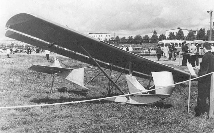
The BRO-11 is a braced two-strut monoplane featuring a high-mounted wing. Its unique construction includes suspended ailerons that span almost the entire wing, kinematically linked to the elevator. The glider’s primary structure is made of wood, predominantly aviation pine for wooden parts and three-layer aviation plywood for covering and gussets, complemented by a small number of metal components.
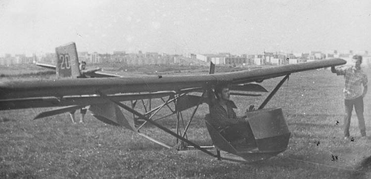
Metal parts, such as washers, plates, fairing tape, and control horns, utilized materials like carbon sheet steel (grade 25), round steel (grade 25), steel tubes (grade 20A), and Duralumin D16. Unlike most training gliders, the BRO-11 lacks a conventional fuselage; instead, it features a flat power truss to which the wing, ailerons, tail unit, floor, nose fairing, seat, stick, pedals, and landing skid are attached.
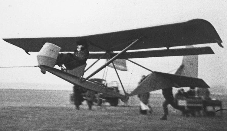
The glider can be launched using an 18mm rubber shock cord, 30 meters long, or a low-power winch. Its light weight also makes it suitable for use as a ground training simulator. The wing is assembled in two sections and fastened to the fuselage truss at the spar root, rear stringer, and to the strut at the spar’s mid-section.
Operational Experience and Modifications
During its operational life, the need for various modifications to the BRO-11’s components became apparent, though not all were formally integrated into the blueprints. Reinforcements included strengthening the skid box with increased slat section, a taller lower shelf, widened 8mm plywood side plates, and a steel shoe replacing the ash wood skid. The front upper end of the tail truss was also reinforced.
Additionally, the strut attachment nodes were replaced with new ones made of two 1.5mm thick steel plates, featuring two holes for the strut attachment bolt and a mooring bolt. The span of each aileron was reduced by approximately 120 mm from the outer ends, and the upper tip of wing strut 62 was redesigned for a universal joint. A separate plate for brace attachment was fitted onto the splice bolt on the outer side of the strut tip.
Performance and Areas for Improvement
The BRO-11 largely satisfied many requirements for initial training gliders, proving to be sufficiently safe. In the event of speed loss, it parachutes instead of nosing down, attributed to its unique aerodynamic layout. Its low specific load and entirely split wing allowed for very low-speed flights, and the glider demonstrated good stability in flight, with effective though not overly sensitive controls.
The glider’s compact size and low weight significantly reduced material consumption by three to five times compared to gliders like the A-1 or BRO-9, making it half the cost of a BRO-9. This also lowered packing and shipping costs, enabling the disassembled BRO-11 to be sent by rail in a standard freight car. The text also suggested reviving the practice of selling gliders as kits—where bulky parts are sent unassembled—to further reduce costs and empower youth to build their own aircraft.
However, the BRO-11 suffered from low “survivability” and a short service life due to frequent structural failures, particularly the skid and front diagonals of the tail truss, caused by rough landings inherent to student training. This highlighted a critical need for shock absorption in the landing gear. Furthermore, pilots noted the glider’s very low aerodynamic quality, leading to unauthorized powerful launch methods, and its peculiar control scheme, which maintains a constant nose fairing position relative to the horizon, depriving students of a crucial visual speed indicator. Improving longitudinal stability was also desired.
Technical Specifications
| Modification | BRO-11 |
| Wingspan, m | 7.28 |
| Length, m | 5.17 |
| Height, m | 1.40 |
| Wing area, m2 | 10.50 |
| Empty weight | 58 |
| Normal flight weight | 118 |
| Cruising speed, km/h | 40 |
| Max. glide ratio | 11 |
| Minimum descent rate, m/s | 1.00 |
| Landing speed, km/h | 30 |
| Crew | 1 |
Image and diagram gallery of the BRO-11 Glider
 BRO-11 |
 BRO-11 |
 BRO-11 |
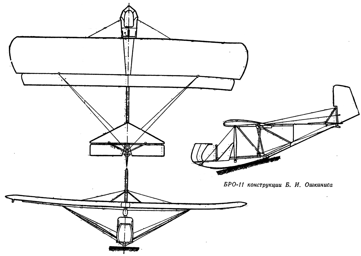 BRO-11 |
ArchivoAéreo Editorial Team
A group of aviation researchers and enthusiasts dedicated to documenting and preserving global aeronautical history. All articles are reviewed to ensure historical accuracy.
Sources & Accuracy
The information presented in this technical sheet has been compiled from declassified flight manuals, historical archives, and specialized literature. While we strive for maximum accuracy, some performance data may vary depending on the specific variant or operational conditions.