BRO-11M Zile
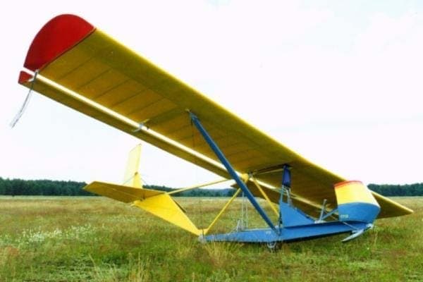
Years of operating initial training gliders, designed by B. Oshkinis, allowed for the identification of their features and shortcomings. These were thoroughly addressed during the design of the BRO-11-M “Zile.” The wing of the BRO-1-M glider features a very simple and typical design, which can serve as a basis for independent design and construction of similar aircraft.
This is confirmed not only by B. Oshkinis’s own work, having created several glider variants with this specific wing, but also by many enthusiasts who built various gliders and motor gliders. Of course, strength requirements must be considered in each individual case: the wing discussed in this article is designed only for operation with a winch (ЮПШ / PLM-6) and requires appropriate reinforcement if installed on any other aircraft (e.g., a motor glider).
Wing Design and Construction
The BRO-11M wing consists of two symmetrical halves (right and left), made of wood and plywood, which are attached to the fuselage truss via the spar root and the rear stringer. Each half-wing is secured by a strut, with its upper end attached to the middle part of the spar and its lower end to the fuselage truss.
Each half-wing assembly includes a box spar, 17 ribs, front and rear tip stringers, plywood skinning, gussets, and blocks. Metal fittings are partially installed on the wing frame before assembly (on the spar and ribs); the rest are mounted on the assembled frame. Figure 3 shows the rear wing fitting and the bracing wire lock, both installed after wing assembly on the rear stringer.
The wing spar (No. 11, 1976) consists of two solid pine flanges, 10×20 mm in cross-section, reinforced with 10×10 mm battens, three blocks, fourteen uprights, and two end battens. After assembly, the spar is carefully planed and covered on both sides with 1 mm thick plywood. The root section of the spar, where the fuselage attachment fitting is installed, is reinforced with 1x65x24 mm plywood patches.
The joint and strut fittings are secured with M5x21 bolts, washers, and castle nuts. A pin is used to connect the wing to the fuselage. Both the wing and aileron have a positive washout of approximately +2°, which is done to increase wing effectiveness at high angles of attack (stall occurs first in the middle part of the wing).
All ribs have the same profile and chord but differ in construction. For example, ribs No. 2-9 and 11-14 are I-beam section, assembled with glue and nails from four 5×5 mm battens, two blocks, and a 1 mm thick plywood web with holes (for lightening). The root rib has a reinforced (box section) construction. Reinforced ribs No. 10 and 15 are similar in construction to rib No. 1.
The ailerons are of the suspended type, meaning they are not recessed into the wing as is usually done, but suspended beneath the wing at two points. One hinge is located on the fuselage truss, the other on the bracket of rib No. 10. Their unusually large span, almost equal to the wing’s span, achieves high effectiveness combined with manufacturing and maintenance simplicity.
Tail Unit and Control System
Covering the wing and aileron frame with fabric is a critical operation, as the overall aerodynamics of the glider greatly depend on its quality. Preparation involves thoroughly sanding the surface of all frame parts that will be covered. The best material is aviation percale; if unavailable, satin or calico can be used. It is desirable to cover with a single piece of fabric or make a blank with a minimal number of seams.
The fabric is applied to the frame, previously coated with special aviation glue AK-20 or first-coat aerolac, following the respective technology for each. It is essential to ensure the fabric is well-pressed against all frame elements and uniformly stretched, especially on the plywood-covered leading edge of the wing. After the glue dries, the covering is stitched through the ribs, and seams are sealed with fabric strips to prevent detachment during glider operation.
Further treatment involves coating with aerolac, known as “first-coat enamelite,” for uniform and strong fabric tension and waterproofing. The wing is coated 2-3 times with enamelite, with intermediate drying and fine sanding to remove imperfections. Final painting should be done with light nitro-paints of high opacity (red, yellow, orange) in two to three layers, followed by a thin coat of clear nitro or oil-resin varnish, polished with fine-grained automotive wax paste.
The wing struts are made of pine. To prevent warping, they are glued with epoxy or casein adhesive from two 85×20 mm planks. The planks must be straight-grained, without knots or rot. After gluing, they are processed according to the shown cross-section, and the end parts are planed to specific profiles. These sections are covered with canvas tape (or fiberglass) on epoxy resin, then fitted with upper and lower tips, secured with M6 bolts.
The tail unit consists of fixed parts (fin and stabilizer) and movable parts (rudder, elevators). The fin is connected to the stabilizer by two tubular struts. The stabilizer has a triangular planform, with its frame assembled from a spar, seven ribs, a leading edge, four blocks, and 32 gussets. The spar is made of a 5×35 mm pine strip, reinforced in the middle with plywood.
A metal fitting, serving both for strut attachment and elevator hinge, is made of 2 mm thick D16T duralumin. The rudder, like the elevator surfaces, has a wooden frame with a fabric covering. The assembly technology for these parts is similar to that of the wing and ailerons. When coating them with aerolac, parts should be clamped to a thick board to prevent warping.
Fuselage, Gondola, and Assembly
The control system consists of manual and foot controls. The manual control (stick) is connected to the ailerons and elevator, while the foot control is connected to the rudder. A distinctive feature of the system is its exceptional simplicity in design, assembly, disassembly, and adjustment. All system elements are grouped on the fuselage truss, making it very convenient for operation, preventive inspections, and repairs.
For the “Zile” glider, the term “fuselage” is purely conventional; there is no fuselage as such. Instead, the glider has a flat power truss made of pine beams, to which a gondola is attached from below. This gondola carries the landing gear (250×125 wheel and shock-absorbing skis), the pilot’s seat with a semi-fairing, and controls. Wing consoles with ailerons are attached to the sides, and the tail unit is at the rear. This thoughtful design allows for quick assembly and disassembly of the glider.
The gondola is an aerodynamically shaped box with a frame of pine beams and a working plywood skin of varying thickness. In the middle part of the gondola, there is a niche for the wheel. The front part houses a tow hook and a shock-absorbing device in the form of a metal ski, sprung by a dense rubber ring. A similar ski is installed in the aft part of the gondola.
A unique feature of the “Zile” glider is its elevator control system. When the stick is pulled fully “towards oneself,” the elevators move up, and simultaneously, the ailerons deflect downwards by 10° due to the original kinematics of the steering device. This achieves an active entry into landing angles without a noticeable “nose-up” attitude, making the “Zile” glider very simple to land and significantly reducing the possibility of bounces or “porpoising.”
The first assembly of the finished glider should take place in a spacious, well-lit room (10×8 m), marking its main coordinates, longitudinal centerline, and positions of the wings and tail unit on the floor with chalk. Plumb bobs must be lowered from the ceiling (or a specially stretched wire) directly above the centerline to ensure correct installation of the wings and tail, eliminating potential misalignments.
The gondola should be temporarily secured to the floor with blocks and supports, after which the tail truss and wings can be mounted. Special light trestles should be made for quick and accurate assembly. The correct geometric shape of the glider is ensured by uniformly tensioning the cable bracing. Therefore, when splicing cables, their length must be determined precisely so that the threaded ends of the turnbuckles can be started by hand without excessive force.
Once the bracing wires are in place and uniformly tensioned with turnbuckles, the control cables for the elevators and rudder can be connected and adjusted. They should be tensioned not too tightly, but without slack. Turnbuckles must be secured with soft wire after tensioning the cables. When adjusting rudder control cables, the neutral position of the rudder should correspond to the neutral position of the pedals, and the neutral position of the elevators to the neutral position of the stick. Ailerons, if correctly and carefully manufactured, practically do not require adjustment.
Technical Specifications
| Modification | БРО-11М |
| Wingspan, m | 7.80 |
| Length, m | 5.47 |
| Height, m | 1.50 |
| Wing area, m2 | 11.80 |
| Empty weight | 65 |
| Normal flight weight | 125 |
| Cruising speed, km/h | 40 |
| Max. aerodynamic quality | 12 |
| Minimum rate of descent, m/s | 1.00 |
| Landing speed, km/h | 30 |
| Crew | 1 |
Image and diagram gallery of the BRO-11M Zile
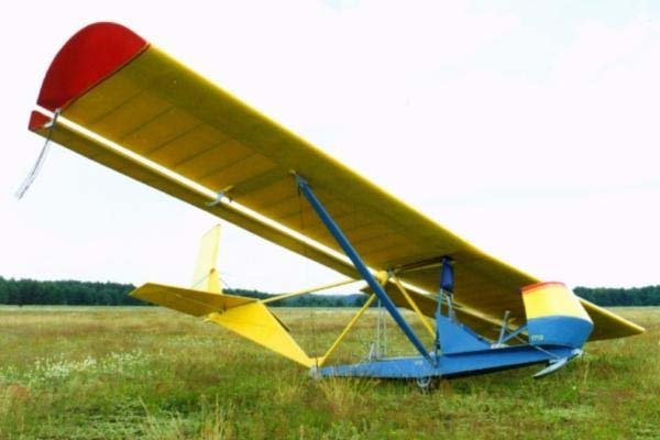 BRO-11M Zile |
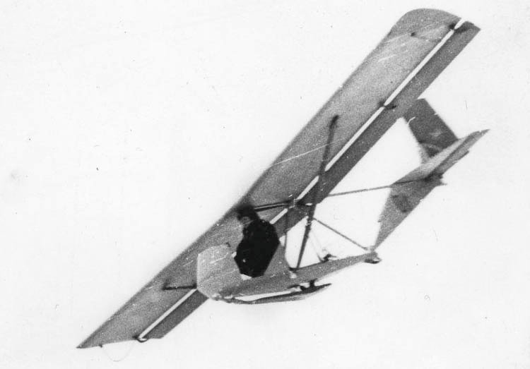 BRO-11M Zile |
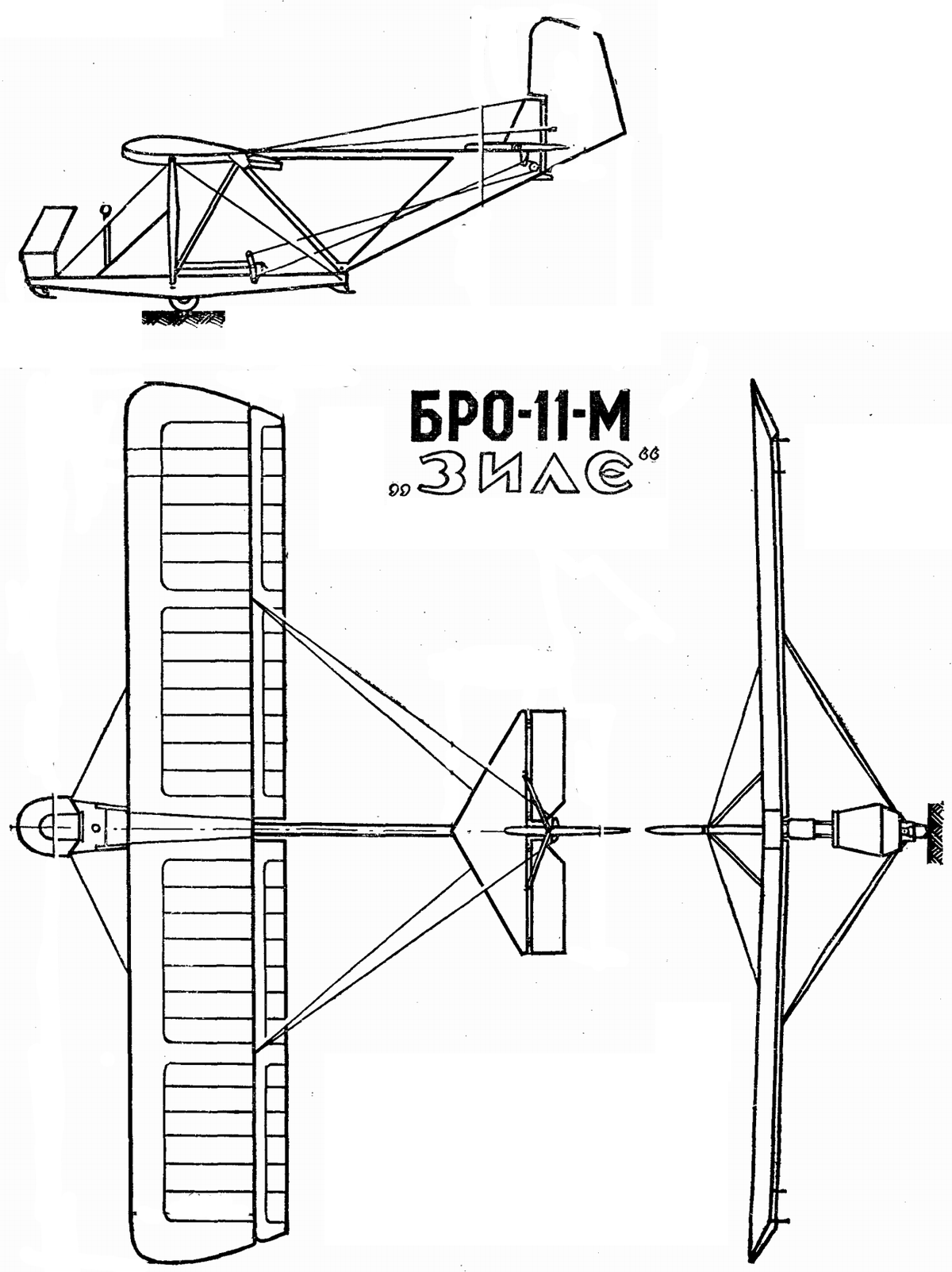 BRO-11M Zile |
ArchivoAéreo Editorial Team
A group of aviation researchers and enthusiasts dedicated to documenting and preserving global aeronautical history. All articles are reviewed to ensure historical accuracy.
Sources & Accuracy
The information presented in this technical sheet has been compiled from declassified flight manuals, historical archives, and specialized literature. While we strive for maximum accuracy, some performance data may vary depending on the specific variant or operational conditions.