BRO-9
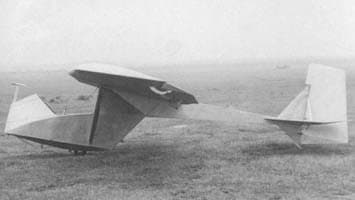
Introduction and Basic Design
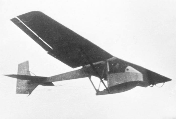
In 1953, flight tests were conducted on the new BRO-9 training glider, designed by B. I. Oshkinis. Tests showed that the glider possessed good stability and controllability, along with higher aerodynamic quality than the A-1 glider. The glider was easy to assemble and disassemble, making it convenient for transport.
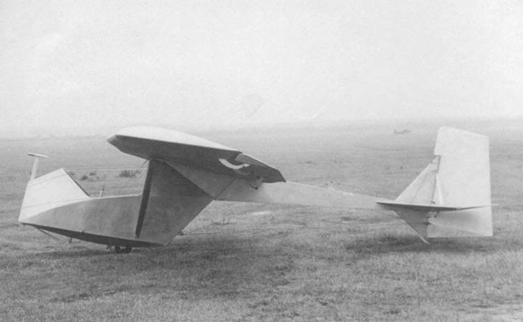
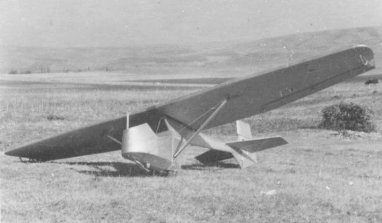
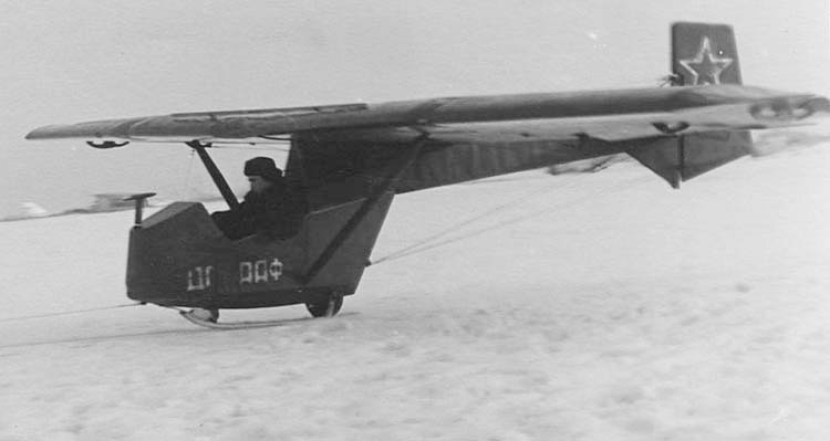
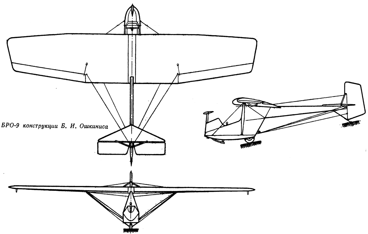
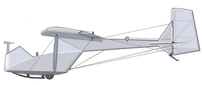
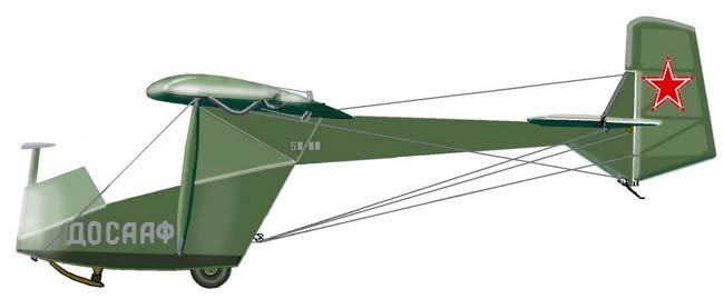
The BRO-9, similar in design to the A-1 glider, was a two-strut high-wing monoplane featuring a braced skid, tail boom, and braced empennage. It was smaller in dimensions than the A-1 and equipped with a wheeled landing gear plus a landing skid. Its construction was entirely wooden, with only a small number of metal components.
Construction Features and Flight Characteristics
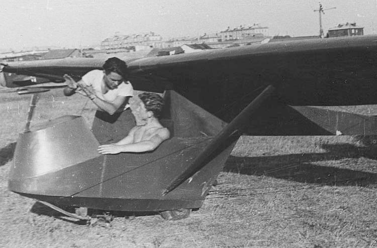
Similar to previous gliders, the gondola and tail boom served as the fuselage. The gondola frame consisted of two base beams, five bulkheads, upper and lower spar belts, an upper beam, a brace, a nose cover, an instrument panel, a floor, bosses, battens, overlays, and gussets. The base beams, made of two pine boards covered on both sides with 1 mm plywood, were located beneath the pilot’s cockpit along the entire fuselage.
The wing, composed of two halves, was secured at two points to the gondola’s upper beam. Its planform was rectangular in the middle, tapering slightly towards the ends with a small rounding. The NACA 4312 wing profile was consistent across the entire span, featuring a negative twist of -3°. Brackets on the upper wing surface allowed for attaching a removable brake slat, used to reduce aerodynamic quality and lower lift during ground run training. The ailerons were slotted, and the stabilizer was placed forward of the fin on the tail boom.
For takeoff, landing, and transport, the BRO-9 was equipped with a semi-balloon type wheel (300×25 mm) and a skid. The wheel was mounted on two brackets between the gondola’s base beams. Manual control was cable-driven, comprising a stick articulated on a shaft bracket, while foot control utilized pedals and linkage. The instrument panel displayed an altimeter, airspeed indicator, and variometer, powered by an air pressure receiver.
Operational Experience and Limitations
The BRO-9 glider, like the A-1, was suitable for both initial training and soaring flights over slopes in updrafts. Despite an unusually low aspect ratio (5.7) for gliders, the BRO-9 exhibited higher aerodynamic quality than the A-1. This was attributed to a better wing planform, an efficiently sustained profile with a high lift coefficient, and reduced drag due to fewer struts, a more streamlined cockpit, and smaller empennage.
However, the BRO-9 had a tendency to nose over (capotage) upon landing, meaning a sharp drop of the nose followed by flipping onto its tail, often resulting in rudder damage. This capotage was likely caused by the wheel’s position being too far back relative to the glider’s center of gravity. Training on the BRO-9, especially initial training, was more challenging than on the A-1 due to higher flight speeds and more sensitive controls. Repairing the BRO-9 was also more difficult than the A-1, owing to the complexity of restoring a damaged cockpit. The BRO-9’s design was not fully “developed” as DOSAAF workshops transitioned to manufacturing the new BRO-11 training glider in 1954.
Technical Specifications
| Modification | БРО-9 |
| Wingspan, m | 8. 75 |
| Length, m | 5.60 |
| Height, m | 1.56 |
| Wing area, m2 | 13. 45 |
| Empty weight | 92 |
| Normal flight weight | 164 |
| Cruising speed, km/h | 66 |
| Max. glide ratio | 14.3 |
| Minimum sink rate, m/s | 1. 16 |
| Landing speed, km/h | 42 |
| Crew | 1 |
Image and diagram gallery of the BRO-9
 BRO-9 |
 BRO-9 |
 BRO-9 |
 BRO-9 |
 BRO-9 |
 BRO-9 |
 BRO-9 |
 BRO-9 |
ArchivoAéreo Editorial Team
A group of aviation researchers and enthusiasts dedicated to documenting and preserving global aeronautical history. All articles are reviewed to ensure historical accuracy.
Sources & Accuracy
The information presented in this technical sheet has been compiled from declassified flight manuals, historical archives, and specialized literature. While we strive for maximum accuracy, some performance data may vary depending on the specific variant or operational conditions.