C-17 Globemaster III
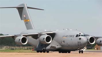
In the 1980s, the primary mission of US military transport aviation, in the event of a military conflict between NATO and the Warsaw Pact countries, was considered to be the transportation of troops across the Atlantic Ocean, from the USA to Western Europe. In 1981, US Air Force (USAF) studies determined the minimum necessary volume of strategic transatlantic air transportation to be approximately 96 million ton-kilometers per day.
However, the fleet of aircraft available to the Military Transport Command in the 1980s (primarily Lockheed C-5s and C-141s, as well as civilian reserve military transport aircraft from CRAF) only provided strategic transport at a volume of 66.3 million ton-kilometers per day. To close this gap, the USAF initiated a program to create a new generation “truck,” the C-X, capable of participating in the establishment of a transatlantic “air bridge” and also used for landing troops in the context of a full-scale war in Western Europe, where major NATO airfields could be destroyed or disabled.
The USAF required a heavy, long-range aircraft, capable of aerial refueling and optimized, first and foremost, for transporting oversized cargo between theaters of operations, delivering it directly to combat zones. This placed increased demands on the takeoff and landing characteristics and combat survivability of the new machine.
A request for proposals for the C-X program was issued to the industry in October 1980. Leading US aircraft manufacturers—Boeing, Lockheed, and McDonnell Douglas—participated in the project competition. On August 28, 1981, McDonnell Douglas was announced as the lead developer. The participants’ interest in winning the competition is evidenced by the fact that McDonnell Douglas spent $40 million of its own funds on preparing the C-X program proposal and the aircraft’s preliminary design.
The preliminary design of the C-X aircraft began in January 1982, and on December 31 of the same year, a $3.4 billion contract was signed for the full-scale development of the aircraft (which received the military designation C-17A) and the construction of three prototypes (one for flight and two for static testing).
Construction of the first aircraft began on November 2, 1987. According to initial plans, its first flight was scheduled for August 1990; however, due to a number of delays caused by both technical and financial reasons, it did not occur until September 15, 1991.
Without waiting for the start of flight tests, a $604 million contract for preparation for serial production and the construction of two production aircraft was signed on January 20, 1988. Assembly of the first of these was completed at the Long Beach aircraft plant on December 21, 1990, and its first flight took place on May 18, 1992. In February 1993, the C-17A was named “Globemaster III.”
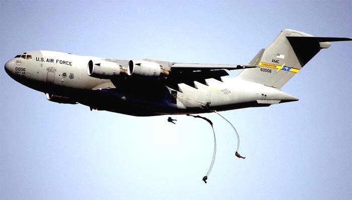
Meanwhile, the USAF conducted intensive prototype tests: the first aerial refueling took place on April 11, 1992; in May, a maximum speed of 944 km/h (M=0.875) was recorded; on June 17, the cargo ramp was opened in flight for the first time; and on July 9, 1993, the first parachute drop was performed. The maximum cargo dropped from the C-17A was 18,160 kg. On May 25, 1994, the prototype C-17A made its first transatlantic flight, landing in the UK.
Early Development and Testing
During flight tests, a number of problems arose, primarily related to the development of onboard software and the integration of the engines and airframe. Specifically, in early 1992, it was discovered that the engines’ specific fuel consumption exceeded the contractually agreed-upon rate by 28%. Modifications were proposed that were expected to reduce the excess fuel consumption to 16% by August 1993 and completely “close” the problem by May 1995.
The flight test program concluded on December 15, 1994, by which time 16 production aircraft had already been delivered to the customer, the USAF.
In 1991 and 1992, static tests began on specially built aircraft. In the autumn of 1992, after the aircraft’s wing suffered premature damage during static strength tests at 128% of the maximum operational load (whereas requirements stipulated strength retention at 150% of maximum operational load), the USAF and McDonnell Douglas commenced work to modernize the aircraft’s structure and systems, necessary to enhance its strength.
The primary solution was to strengthen the wing by using steel doublers on aluminum stringers and reinforcing the stringers themselves. In the future, it is planned to install an active load-control system (ACLS) on the aircraft, which, by engaging ailerons and spoilers, will mitigate the impact of wind gusts on the airframe structure (similar systems are already used on the Airbus Industry A340 airliner, the Lockheed C-5 military transport aircraft, and the Northrop B-2 bomber).
During its implementation, the C-17A program was repeatedly subjected to sharp criticism from Congress and the military, due to design flaws and poor program management. It was noted that the C-17A was overweight by several thousand kilograms, its development schedule was many months behind, and the aircraft’s engines could not operate at full thrust due to exhaust gases overheating the aluminum flaps. In their defense, the developers claimed that the USAF had changed and increased the aircraft’s requirements after the contract was issued in 1981, which complicated adherence to the schedule and increased technical risk. Additionally, excessive government intervention also slowed the program.
In May 1993, Secretary of Defense Les Aspin fired Major General M. Buchko, the C-17 aircraft program director, for improper management of its implementation. Three other high-ranking USAF officers were also disciplined.
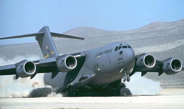
However, work on the new aircraft continued, as none of the possible alternatives could serve as a full replacement for the C-17A. C-5 and C-141 aircraft were only capable of operating from 850 out of 10,000 runways worldwide (excluding CIS countries and China). Only the C-130 could operate from short, unprepared runways.
The C-17A is designed to transport almost twice the cargo compared to the C-141 and C-130, and deliver it directly to the theater of operations without transshipment to other aircraft. Furthermore, loading and unloading of the C-17A occur significantly faster.
According to initial plans, the USAF was to receive 210 C-17A aircraft by 2000, with the full program cost estimated at $37.1 billion, and the price of a fully equipped aircraft at $125 million (excluding R&D and other overhead costs). In 1991, the order volume was reduced to 120 aircraft, with procurements expected to be completed in fiscal year 2003 and deliveries in 2004.
According to 1992 estimates, the total program cost would amount to $35.802 billion. McDonnell Douglas’s expenditures for the development and initial production of the C-17A are estimated at $7.45 billion. More than 15,400 working drawings are required for the construction of the Globemaster III, and the maximum number of McDonnell Douglas specialists involved in the program is 10,000 people. In addition, approximately 200 subcontractors are engaged in the program, the main ones being Pratt & Whitney (engines), LTV (tail unit and engine nacelles), and Lockheed (wing components).
Strategic Capability and Global Role
C-17 aircraft are primarily intended for deploying light infantry divisions to Western Europe (up to 10 divisions in less than two weeks). A distinctive feature of the aircraft is its ability to transport cargo not only between theaters of operations but also within a single theater, landing on small, minimally prepared airfields. The Globemaster III combines the characteristics of the previously developed strategic military transport aircraft C-5 (transport of oversized cargo) and the operational-tactical airlifter Lockheed C-130 (ability to operate from runways measuring 915×27 m). The design of the C-17A was significantly influenced by the Soviet Il-76, which, like the Globemaster III, also combines strategic and operational-tactical transport properties.
Undoubtedly, American designers carefully studied the Ilyushin Design Bureau’s aircraft, borrowing several important features from it. Like the Il-76, the American aircraft can operate autonomously for extended periods at airfields lacking special equipment.
The ability to deliver cargo from US airbases directly to potential combat zones in Western Europe allows for the offloading of rear airfields, eliminates the need to transship equipment onto tactical aircraft, and reduces the demand for tactical airlifters. In the late 1980s, there were only 47 airfields in West Germany suitable for C-141 operations and 18 for C-5s. In contrast, the C-17A can “work” from 132 German airfields.
Other important features of this aircraft include: the ability to move backward using thrust reverse on runways with an uphill slope of 2 degrees, with maximum load at an air temperature of 32°C; the ability to land with a glideslope angle of 5 degrees (instead of the usual 2.5-3 degrees), which allows landing no more than 150 meters from the runway threshold; and superior maneuverability compared to other military transport aircraft in flight and on the ground (its minimum turning radius on the ground is 27.4 m, significantly less than the C-5’s 45.1 m; as a result, eight C-17As can be placed in a 46,450 m² parking area, while only three C-5s fit).
The contract stipulates that the company guarantees the required values for about 20 reliability and operational maintainability indicators, including a maintenance labor intensity of 18.6 man-hours per 1 hour of flight (compared to 35 man-hours for the C-5B). To replace a C-17A engine, only 16 man-hours are needed (compared to 40 man-hours for the C-5B). Under a contract issued in late 1988, Flight Safety was to supply the USAF with 12 six-degree-of-freedom C-17 simulators, which would replicate flight conditions during the day, at dusk, and at night. The first simulator was delivered to the customer in March 1992.
The high cost of the C-17A compels the company to seek additional areas of application for the aircraft to expand its market. In the mid-1990s, a civilian variant of the Globemaster III, the MD-17, was proposed, stripped of specific military systems and equipment. However, there is no information on contracts being awarded for this machine.
Proactively, Boeing, which acquired McDonnell Douglas in 1996, is working on a KC-17 tanker aircraft, intended to replace the Boeing KC-135R and KC-135T “Stratotanker” tankers in the USAF. Blocks with specialized refueling equipment (both telescopic boom and hose-and-drogue methods), designed as separate quick-detachable modules, can be mounted in a relatively short time on the airframe of a standard C-17A military transport. Additionally, the KC-17 tanker is expected to receive an additional fuel tank located in the center wing box, which will increase the total tank capacity to 102,294 liters, and with the installation of modular fuel tanks in the cargo compartment, up to 165,909 liters.
Another proactive development by the company is a strategic variant of the C-17A transport aircraft, intended to replace the C-5. This aircraft would have a fuselage lengthened (depending on the variant) by 3.6 or 12.0 meters, as well as an increased payload capacity. Should the USAF decide to procure these aircraft, they could enter service after 2006.
In mid-November 1998, the USAF received the 44th of the 120 ordered Boeing C-17 Globemaster III operational-strategic military transport aircraft, with delivery of the entire batch expected to be completed by 2005. However, the USAF and Boeing are already planning to begin the first phase of C-17 modernization. At Boeing’s technical service center in Texas, unified integral processors (CIPs), supplied by Lockheed Martin, are planned for installation on the first 40 aircraft of this type.
New processors will reduce the aircraft’s life cycle cost and expand the capabilities of the onboard navigation system (specifically, enabling a digital mapping database with “digital map” display on onboard screens) and the electronic warfare suite. On all later production aircraft (starting with the 41st C-17), CIPs are installed during manufacturing.
Other planned improvements for the C-17 during scheduled modernization include a global route flight control system, new equipment for installing stretchers with wounded, a more advanced cargo drop management system, and means to increase the accuracy of approach and landing control at a given point.
In later stages of modernization, it is planned to refine the aircraft’s software, its electronic warfare suite, and a number of other onboard systems.
Rejecting claims by several media outlets that the C-17 did not fully meet STOL (short takeoff and landing) performance requirements, USAF representatives stated that this type of aircraft had already demonstrated the ability to land on a 914-meter runway with a 72-ton load and take off from the same runway with a 33-ton load.
Currently, the C-17 is the most modern operational-strategic military transport aircraft in the world, surpassing its Russian counterpart, the Il-76MD, in several parameters. Unfortunately, work on creating a new modification of the “seventy-sixth” — the Il-76MF — has been significantly delayed. The program for developing the fifth-generation operational-strategic aircraft Il-106 is also practically frozen. Thus, the Globemaster III will long remain the world leader in its weight category.
Design Features and Technology
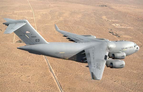
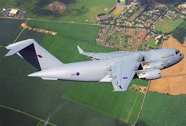
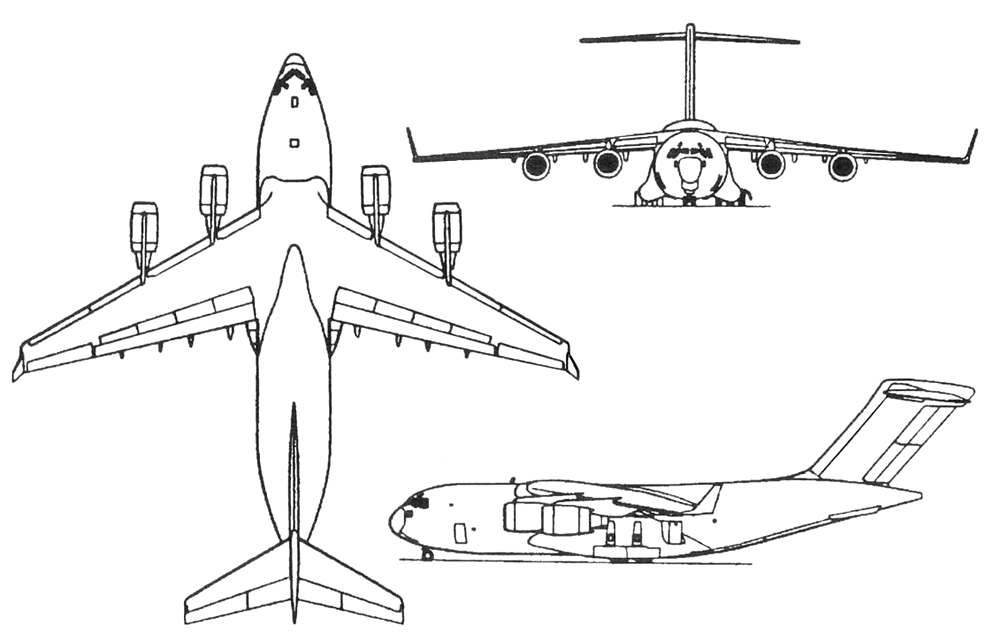
The aircraft is designed according to a conventional aerodynamic scheme with a large-diameter fuselage, high-mounted wing, and T-tail. The airframe is primarily constructed from aluminum alloys, with composite materials accounting for 10-15% (control surfaces, wingtip surfaces, landing gear doors, fairings, and radomes). The guaranteed airframe life is 30,000 flight hours, of which 10,000 must be flights at an altitude of 90 m.
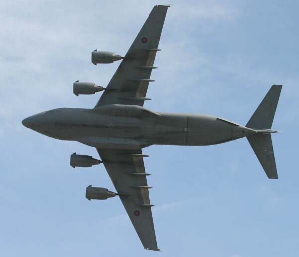
The wing has a sweep angle of 25 degrees and a supercritical airfoil, with an aspect ratio of 7.2. The wingtip aerodynamic surfaces (winglets), also with a supercritical airfoil, are 2.9 m high, have an area of 3.33 m², a sweep angle of 30 degrees, and a side inclination angle of 15 degrees from the vertical. The wing skin is made using 26.82 m long panels—the largest aluminum alloy aircraft components abroad by the late 1980s. The ailerons are among the largest composite material structural components: one aileron has an area of 5.9 m², a length of 6.4 m, a tip chord of 0.76 m, and a root chord of 1.32 m.
Wing mechanization includes full-span leading-edge slats and double-slotted flaps with engine exhaust blowing, developed based on the energized mechanization of the YC-15 experimental aircraft and occupying approximately 2/3 of the wing span. The flaps can be set in any intermediate position to optimize the flight mode. Flap deflection reduces the stall speed in landing configuration by 46 km/h. Forward of the flaps on each wing console are four sections of spoilers.
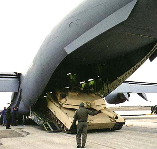
The semi-monocoque fuselage has an upward-sloping aft section, beneath which are two aerodynamic strakes. The cargo compartment features a rear loading ramp that can accommodate cargo weighing up to 18.1 tons in flight. The ramp is four-section with hydraulic drive and can be set at various angles depending on the type of equipment being loaded. Tie-down points, rated for a load of 11.3 tf, are located in the cabin at 0.61 m intervals. Loading and unloading equipment includes rail guides and a roller conveyor.
The cargo compartment can accommodate an M1A1 tank, M2/3 infantry fighting vehicles, 45-ton trucks (two abreast), jeeps (three abreast), a 155 mm self-propelled artillery system, up to three AH-64 “Apache” attack helicopters, and up to 18 463L containers with cargo. There are 54 non-removable folding seats for personnel transport, and an additional 48 seats (to accommodate six abreast) are planned to be stored on board the fuselage; racks for securing 12 stretchers are installed on the sides. The lower part of the fuselage is armored for protection against small arms fire. Non-stop airdropping of cargo on platforms from extremely low altitudes using extraction parachutes (LAPES system) or dropping up to 102 paratroopers is possible.
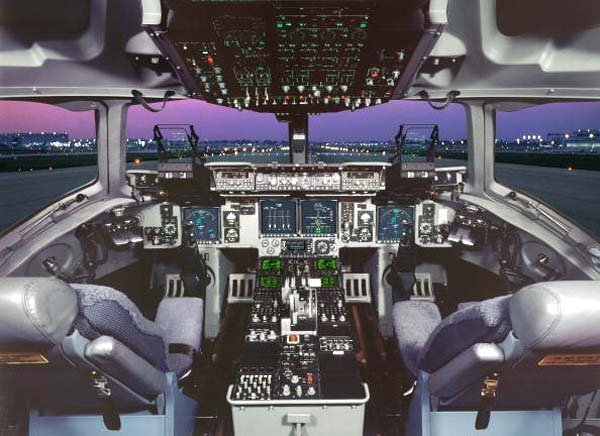
The typical crew consists of three people: a commander, a co-pilot (whose seats are adjacent), and a cargo handling equipment operator, whose workstation is on the right side under the raised floor of the cockpit. Additionally, there are seats for two observers. Entry to the cockpit is via a door with an integrated ladder, located on the left side. The cockpit glazing has increased bird strike resistance. A crew rest compartment, which is a fully autonomous module similar to those used on passenger aircraft, is located on the left side directly behind the cockpit.
The tail unit is T-shaped with swept fin and stabilizer. The stabilizer span is 19.81 m, with an area of 79.2 m². The elevators are two-section, with the inner section measuring 4.45 m in length. The rudder is a two-section, two-segment design, with a height of 3.4 m.
The landing gear is a retractable tricycle type with hydraulic actuation and the capability for emergency gravity deployment. It is designed for landing at a descent rate of 4.57 m/s and for operation from both paved and unpaved runways. The nose gear has two wheels and retracts forward. The main landing gear units have six wheels with two sequentially arranged single-axle three-wheel bogies, retracting into fairings on the sides of the fuselage. The braking system allows the aircraft, moving at 240 km/h, with a mass of 228 tons, to stop within 490 m in 14 seconds. The landing gear track is 10.27 m, and the wheelbase is 20.05 m.
Power Plant: Four engines are located in underwing nacelles on pylons. The F117-PW-100 turbofan, of modular design, is a variant of the civilian PW2040 engine (installed on the Boeing 757) and features a single-stage fan, a four-stage low-pressure compressor, a 12-stage high-pressure compressor, a two-stage high-pressure turbine, and a five-stage low-pressure turbine. Thrust reversers are installed for use on the ground and in flight; gases during reverse thrust flow upwards to prevent dust ingestion by the engines or damage to the airframe and engines by foreign objects. An electronic engine control system and an active radial clearance control system are installed. The Garrett GTCP331 APU is installed in the right main landing gear bay.
The engine length is 3.729 m, fan casing diameter 2.154 mm, dry engine mass 3,220 kg, bypass ratio 6.0, pressure ratio 31.8, air consumption 608 kg/s, and specific fuel consumption in cruise mode at M=0.8 at an altitude of 10,670 m is 0.563 kg/kgf·h.
Fuel is stored in tanks with a total capacity of 102,614 liters. An in-flight refueling system is available.
Aircraft Systems: The flight control system is a digital fly-by-wire (FBW) with a four-channel redundancy scheme and actuation of control surfaces (ailerons, elevators, and rudder) by two hydraulic systems. Each channel uses a General Electric computer. There is a backup control system with mechanical linkage to the hydraulic actuators. (During a test flight on October 17, 1991, on the prototype T-1, all four FBW channels automatically disengaged and switched to the mechanical system, which was then used for landing. This was caused by excessive data spread from four air pressure sensors located on the fuselage due to airflow distortion from a boom with sensors installed in the nose section of that particular aircraft. After this incident, by the end of 1992, software changes were implemented to ensure the FBW would transition to a mode with fixed gain coefficients rather than disengaging, even with a complete loss of airspeed signal.)
The control stick is of a new type: the entire stick deflects for pitch control, and only the upper quarter for roll control. A stability and control augmentation system is present. Aircraft tests at high angles of attack showed the need for an angle of attack limiter and revealed an insufficient level of natural stall warning cues with flaps extended, requiring the implementation of an automatic stick shaker.
Mission Equipment: The instrument equipment includes two Head-Up Displays (HUDs), four multi-function color CRT displays, with conventional instruments used as backups, and the possibility of using night vision goggles. Two independent Inertial Navigation Systems (INS) with ring laser gyroscopes are used, integrated for the first time on a military transport aircraft with a digital flight management system, an onboard autonomous inert gas generation system (OBIGGS), a Bendix AN/APS-133(V) weather radar, and a satellite navigation system receiver.
Electronic equipment features connecting devices made with surface mount technology and flexible circuits.
Technical Specifications
| Modification | C-17A |
| Wingspan, m | 50.29 |
| Aircraft length, m | 53.04 |
| Aircraft height, m | 16.79 |
| Wing area, m2 | 353.02 |
| Empty equipped weight | 122016 |
| Maximum takeoff weight | 263083 |
| Internal fuel, l | 102615 |
| Engine type | 4 Turbofan Pratt Whitney F117-P-100 |
| Thrust, kN | 4 x 185.49 |
| Maximum speed, km/h | 830 |
| at high altitude | 804 |
| at low altitude | 648 |
| Ferry range, km | 8710 |
| Practical range, km | 4450 |
| Operational radius, km | 925 |
| Service ceiling, m | 13700 |
| Crew, crew | 3-4 |
| Payload: | 144 soldiers or 102 paratroopers or 48 litters and 54 seated wounded with attendants or a maximum of 78108 kg of cargo, standard – 56245 kg |
Image and diagram gallery of the C-17 Globemaster III
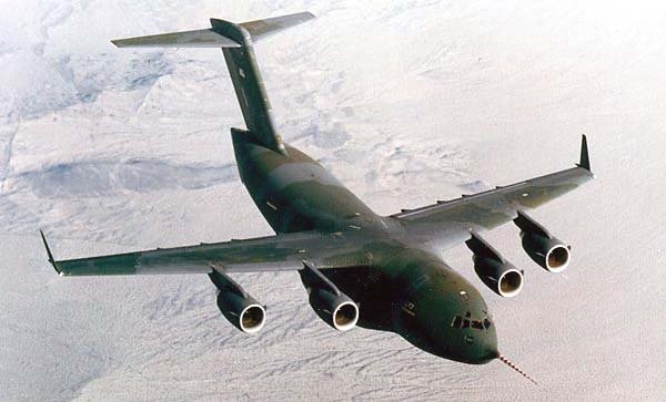 C-17 Globemaster III |
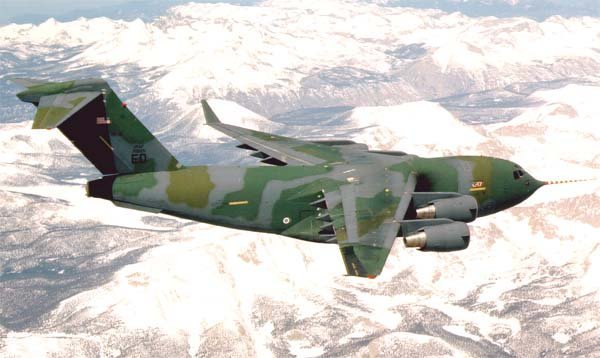 C-17 Globemaster III |
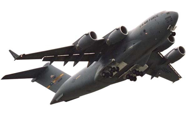 C-17 Globemaster III |
 C-17 Globemaster III |
 C-17 Globemaster III |
 C-17 Globemaster III |
 C-17 Globemaster III |
 C-17 Globemaster III |
 C-17 Globemaster III |
 C-17 Globemaster III |
 C-17 Globemaster III |
 C-17 Globemaster III |
ArchivoAéreo Editorial Team
A group of aviation researchers and enthusiasts dedicated to documenting and preserving global aeronautical history. All articles are reviewed to ensure historical accuracy.
Sources & Accuracy
The information presented in this technical sheet has been compiled from declassified flight manuals, historical archives, and specialized literature. While we strive for maximum accuracy, some performance data may vary depending on the specific variant or operational conditions.