Curtiss BFC-2 Goshawk
Until December 1932, the primary suppliers of single-seat carrier-based fighters for the US Navy were Curtiss and Boeing. Initially, with only one aircraft carrier, the “Langley,” and just two fighter squadrons of carrier aviation, there was little competition between these firms. The military purchased small quantities from both, striving to equally support both alternative sources.
The situation changed in 1927 with the commissioning of the new aircraft carriers “Saratoga” and “Lexington.” Each of these ships could base up to 90 aircraft (for comparison, the “Langley’s” capacity was limited to just 34 aircraft). The number of carrier fighter squadrons tripled, and the Navy’s minimum fighter needs were estimated at 120-150 aircraft. With a cost per fighter at that time ranging from $13,000 to $15,000, the contract sum could exceed 2 million dollars. The struggle for lucrative contracts turned Curtiss and Boeing into ruthless competitors.
Boeing won the battle with its F4B-1 aircraft, and the Great Depression that erupted in 1929 completed the competitor’s utter defeat, making Boeing an absolute monopolist. Over three years of its “undivided dominion,” it sold over 230 F4B aircraft of various modifications to the fleet.
Goshawk Development and First Flights
Unexpectedly for everyone, in December 1932, the little-known Grumman company entered the aviation market, seriously challenging Boeing’s position. The “culprit” of this event was the company’s carrier-based fighter FF-1, with an all-metal construction and retractable landing gear. The following year, luck finally smiled on Curtiss. The Navy took notice of its promising F11C Goshawk fighter and ordered 29 modified aircraft of this type under the designation F11C-2. For the company, against the backdrop of its previous failures, this was a very important step forward.
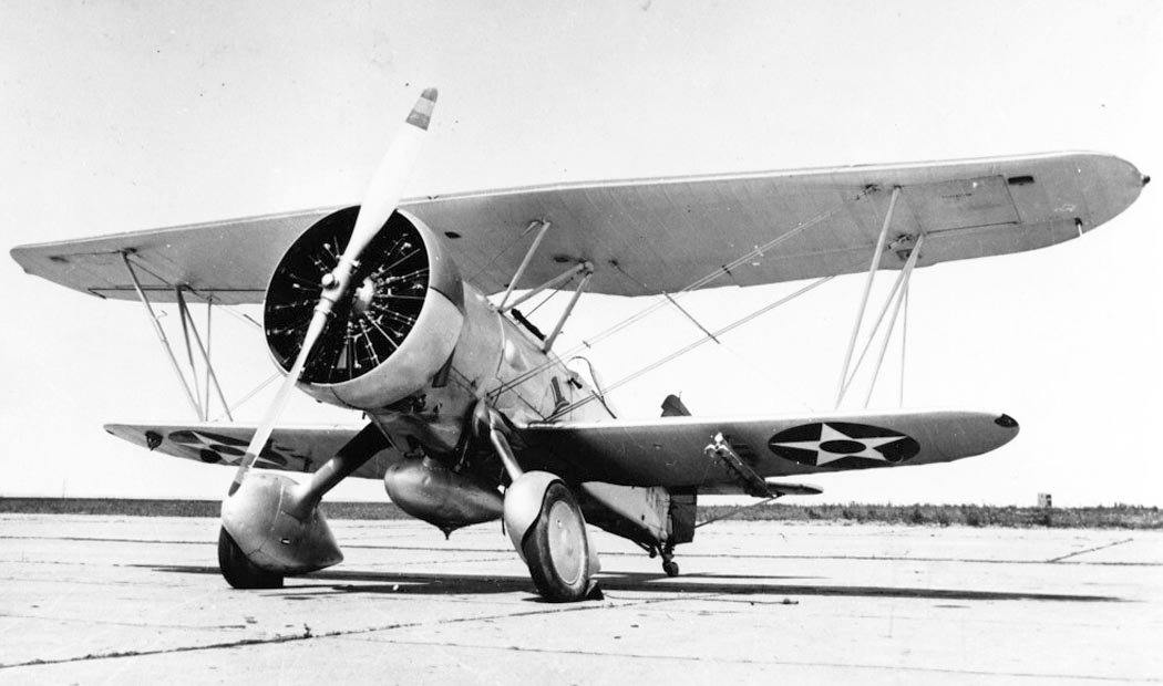
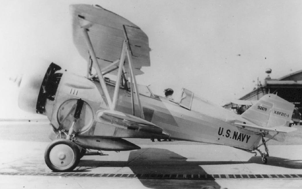
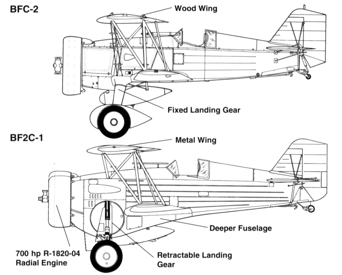
Striving to consolidate its new position and expand supplies, Curtiss’s management decided to use retractable landing gear on the F11C. The new aircraft project received the internal designation “Model 67.” The military supported the company’s innovation, and engineers were given the fifth production F11C-2 aircraft, serial number 9269, for modification. The main landing gear retraction system was not original and almost completely duplicated the scheme patented by Grumman. The landing gear wheels retracted into rounded niches on the sides of the fuselage using a chain drive operated by a handle in the cockpit.
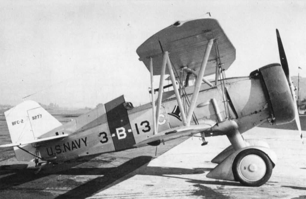
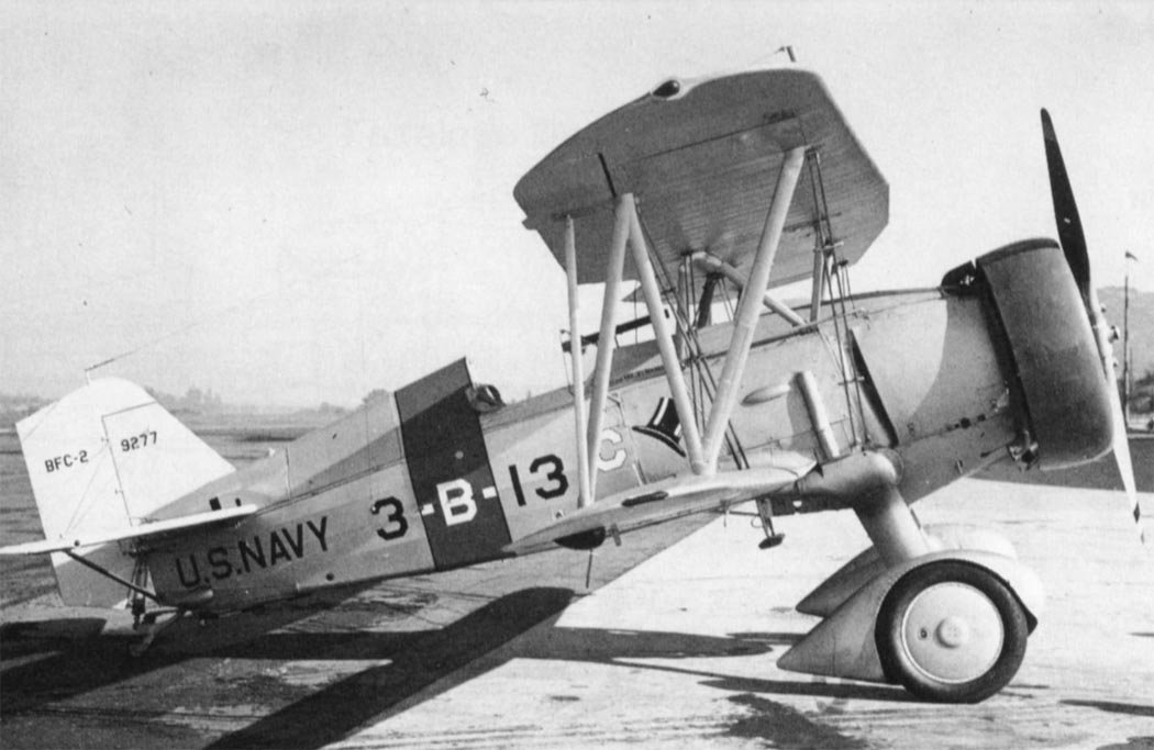
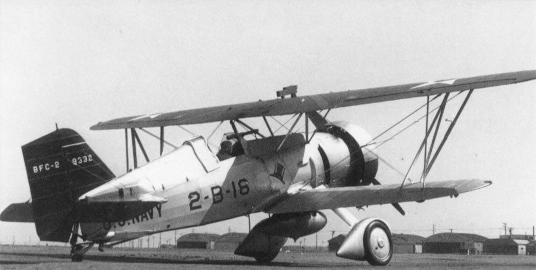
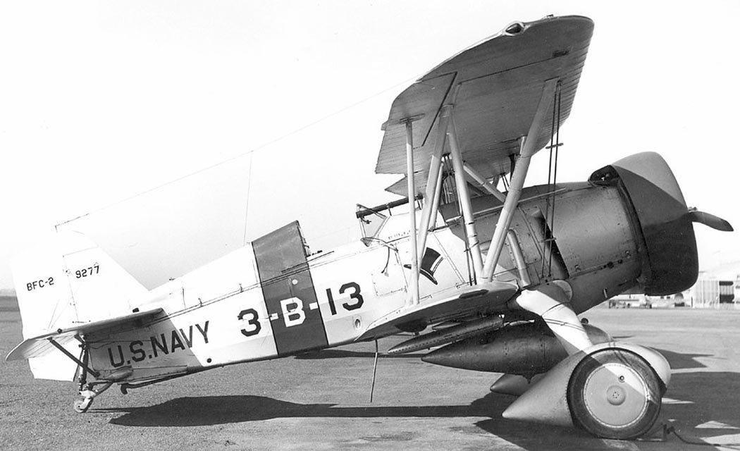
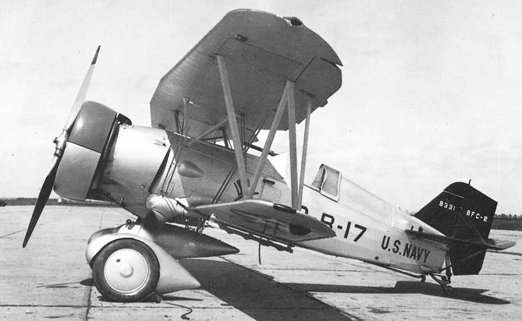
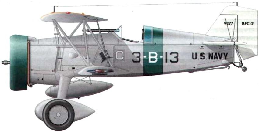
To accommodate the niches and the retraction mechanism, the dimensions of the forward fuselage section were increased. The aircraft’s structural weight increased by 104.4 kg, and to maintain balance, the upper wing was shifted slightly forward from its previous position. Another difference in the new aircraft was the semi-enclosed pilot’s cockpit. If necessary, the pilot could protect themselves from rain or snow with a small sliding canopy. This improvement proved quite useful, and in 1934, a similar canopy was installed on the BFC-2 fighter-bomber modification.
The aircraft’s modification was completed in the spring of 1933, and the Navy assigned the new aircraft the designation XF11C-3. The modernized aircraft made its first flight in April 1933. On May 27, 1933, the fighter was handed over to the Navy for evaluation trials. The report compiled by naval aviators recorded the following characteristics: a maximum takeoff weight of 2181 kg and a maximum flight speed of 348 km/h at an altitude of 2439 m.
The prototype was equipped with a nine-cylinder Wright R1820-80 air-cooled radial engine with 700 hp and a fixed-pitch all-metal propeller. For production aircraft, the company planned to install a ground-adjustable pitch propeller, which promised improved flight characteristics. But even without this, the XF11C-3 surpassed its predecessor F11F-2 in speed by 22.5 km/h. During flight tests, controllable trim tabs were installed on the ailerons and rudder. On February 26, 1934, the Navy ordered a small series of 27 F11C-3 aircraft, all destined for the new aircraft carrier “Ranger.” However, its fighter squadrons were planned to be armed with Boeing F4B-4 aircraft, which led to Curtiss aircraft being assigned the role of fighter-bombers and their designation changed to BF2C-1.
Operational Challenges and Retirement
Changes had to be made to the F11C-3’s design in accordance with its new assignment. A suspension point for a 227-kg bomb or a 189-liter fuel tank was attached in the recess between the landing gear retraction mechanism fairings. Additionally, the wooden wing structure was replaced with a lighter, metal one. During flight tests, the XFB2C-1 prototype crashed on takeoff due to engine failure. This occurred on September 24, 1934, at Hampton Roads airbase in Virginia. The military paid no attention to the incident, as the prototype had flown over 254 hours without issues before then. The order volume and deadlines remained unchanged.
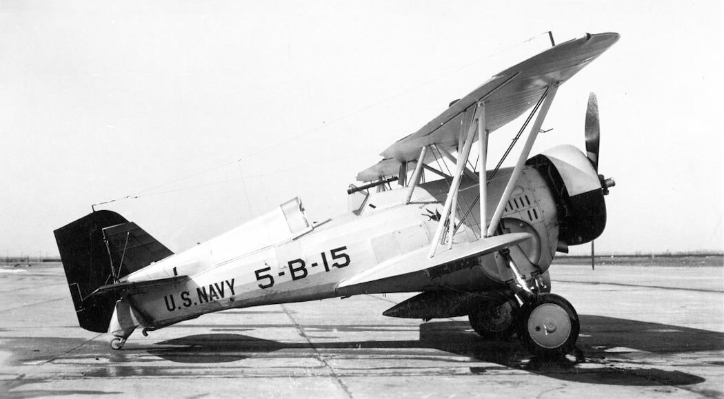
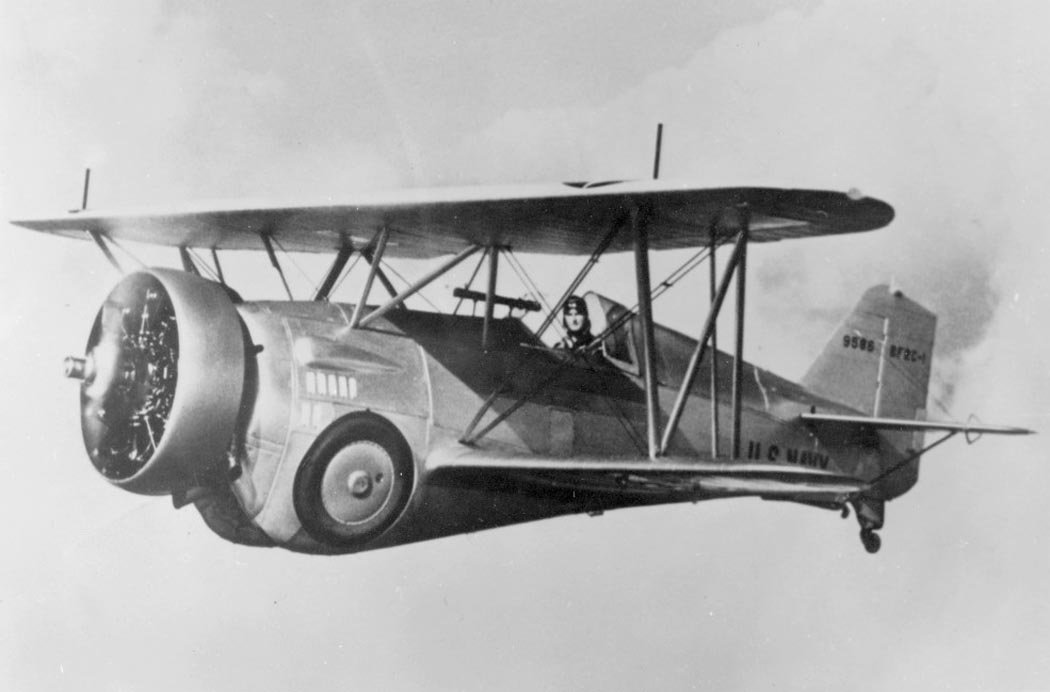
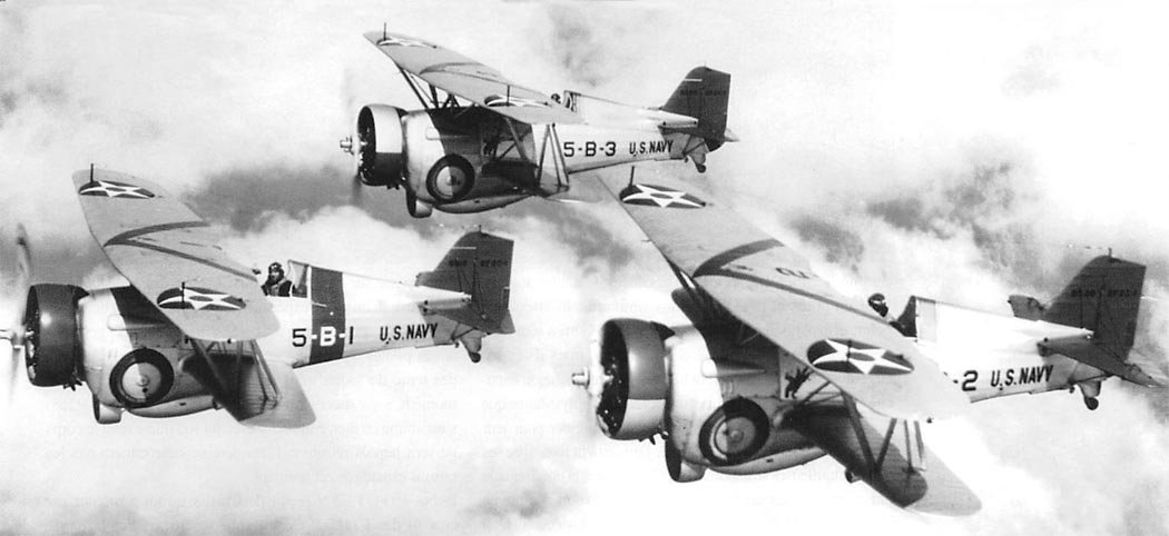
The first production aircraft was handed over to the Navy on October 7, 1934. It was powered by an R1820-04 engine generating 700 hp at an altitude of 2438 m. Production aircraft were sold to the military at a price of $18,000 per unit, with one-third of this sum accounted for by the engine. The outfitting of the VB-5B deck squadron of the aircraft carrier “Ranger” with new aircraft began in November 1934. Sailors used the BF2C-1 as both a fighter and a dive bomber.
In the fighter configuration, the aircraft’s takeoff weight did not exceed 2068 kg, and the maximum speed of the production model was 362 km/h. In the bomber configuration, the aircraft’s weight increased by 241 kg, while the maximum flight speed dropped to 346 km/h. Combat pilots were extremely dissatisfied with the new aircraft. During flight at cruising speed, the wings began to vibrate ominously, turning the FB2C-1 into a flying “perforator.” The cause of this extremely unpleasant phenomenon was identified only after specially arranged bench tests: a coincidence of the natural vibration frequencies of the engine and the wing.
Engineers concluded that the frequency matching of the engine and wing vibrations was to blame. The problem was attempted to be eliminated by attaching weights to the wingtips, changing the harmonic frequencies of their vibrations, but flight tests almost led to disaster. Overloaded struts and wires of the wing box began to break. The company offered the fleet another solution: replace the metal wings of all aircraft with wooden ones from the F11C-3 export variant, which did not exhibit such a tendency to vibrate. The cost of such an operation exceeded all reasonable limits, and there was no great need for it anymore. The fleet had already ordered a large batch of F3F fighters from Grumman, and the BF2C-1 began to be decommissioned to shore units.
The last aircraft was removed from service with the VB-5B deck squadron in February 1935. Before the F3F’s arrival, the unit was temporarily equipped with Boeing F4B-4 aircraft. Another significant drawback of the BF2C was tail vibration when a load was present on the central pylon. This defect was quickly and effectively eliminated by attaching an annular airflow stabilizer in front of the load, which, when viewed from the side, resembled a retractable oil cooler. The failure of the BF2C-1 had serious consequences for Curtiss. The Navy Department raised the question of discontinuing further cooperation with the company in the field of carrier fighter development due to its inability to design satisfactory aircraft. In response, the company attempted to adapt the BF2C-1 for training purposes, but this initiative was rejected.
In January 1937, flights of the BF2C-1 were banned. The remaining 19 operational aircraft were gathered at the San Diego base, where all valuable equipment was removed from them, and the aircraft remnants were loaded onto a barge and dumped into the sea. The BF2C served on aircraft carriers for only four months, setting a unique record for the “shortest service in US carrier aviation.”
The Curtiss Hawk III’s Export Success
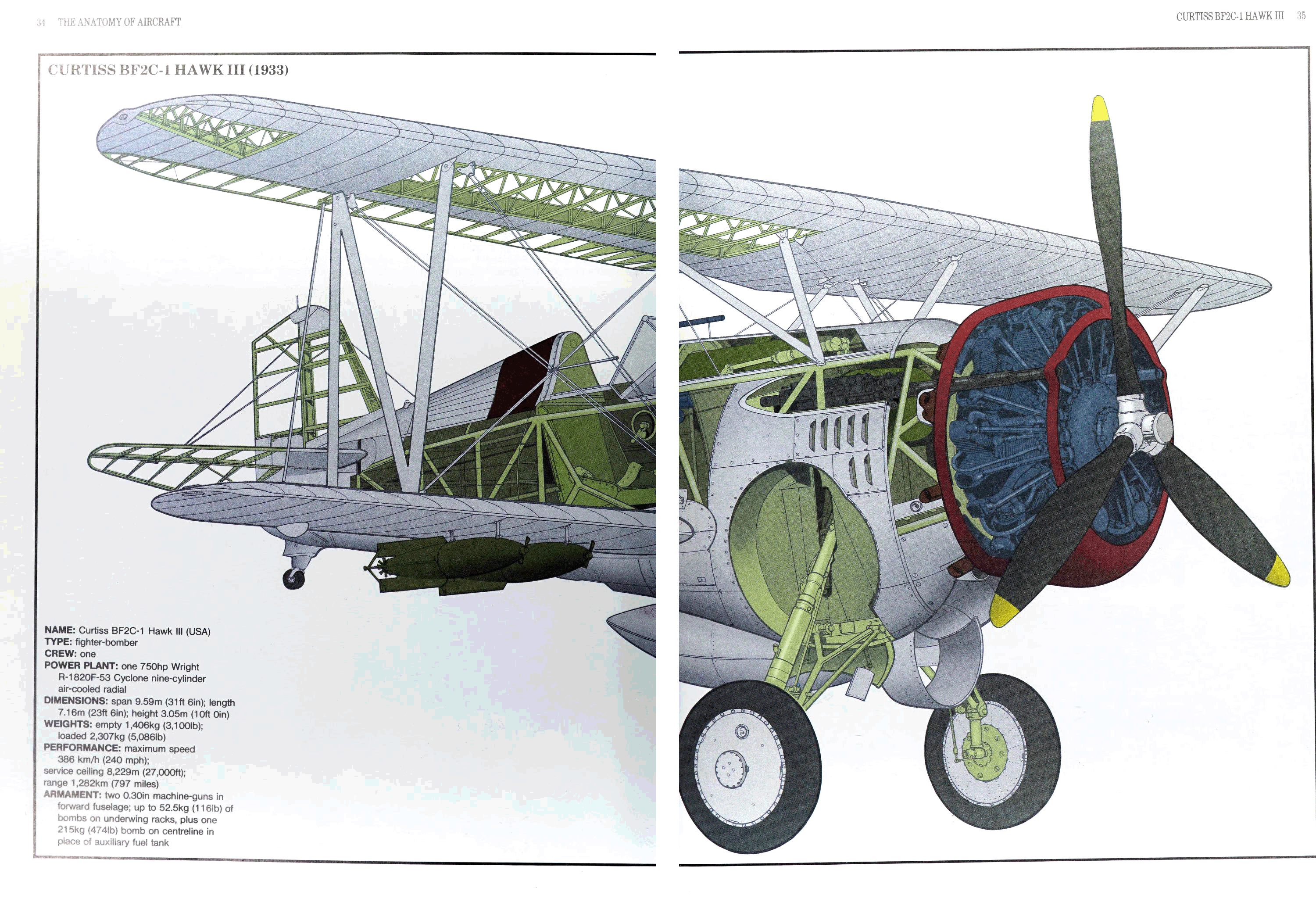
The fate of the land-based variant of the F11C-3 fighter, known as the Hawk III, was more successful. It differed from the carrier version by the absence of a tailhook, a three-bladed propeller, and a wooden wing structure (metal was only used in the aileron frame). The powerplant was the Wright SR-1820F-53 engine from the F11C-2. All aircraft were sold abroad.
In April 1935, one F11C-3 was sold to Turkey. In August, deliveries of 24 aircraft began to Thailand (Siam). The following year, Argentina bought ten fighters. China acquired the largest number of Hawk III aircraft—102 planes were supplied there starting from 1936. Almost all “Chinese” Hawk III aircraft arrived disassembled and were assembled by local workers in aviation workshops.
On August 14, 1937, Chinese Hawk III aircraft engaged Japanese planes in combat. Chinese pilots fought bravely against enemy forces that outnumbered them by 13 times and successfully intercepted bombers. For example, on the first day of the war, they managed to shoot down three Mitsubishi Type 96 (G3M2) bombers. However, it should be noted that these bombers flew without fighter escort, and their fuel tanks were unprotected. When encountering Japanese fighters in the air, the Hawk III’s chances were slim, and not only because of the numerical superiority of the Japanese. Their primary fighter—the Nakajima Type 95 (A4N1)—was almost one ton lighter, and its engine was 30 hp more powerful than the American Wright engine.
In just a couple of months, the Japanese gained air superiority, and after the appearance of A5M monoplane fighters, they destroyed almost all Chinese aircraft. Chiang Kai-shek’s government turned to the USSR for help. In October 1937, the first Soviet fighters, the I-16, I-15, and I-153, began arriving in China. All remaining Hawk III fighters and other obsolete American, Italian, and French aircraft were reclassified as training machines. They occasionally continued to participate in battles and were destroyed by 1941. A total of 139 F11C-3 fighters were built.
Technical Details and Armament
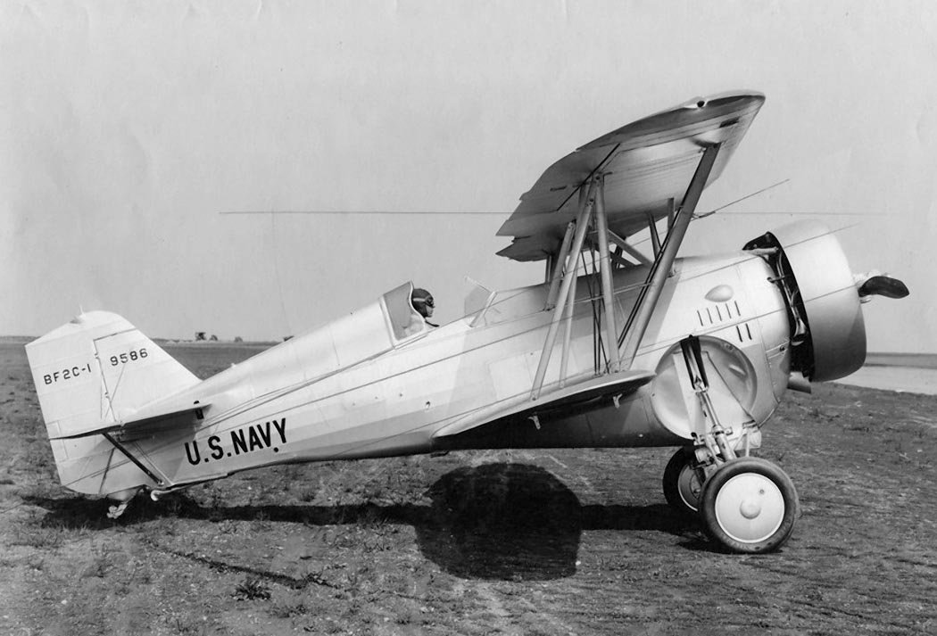
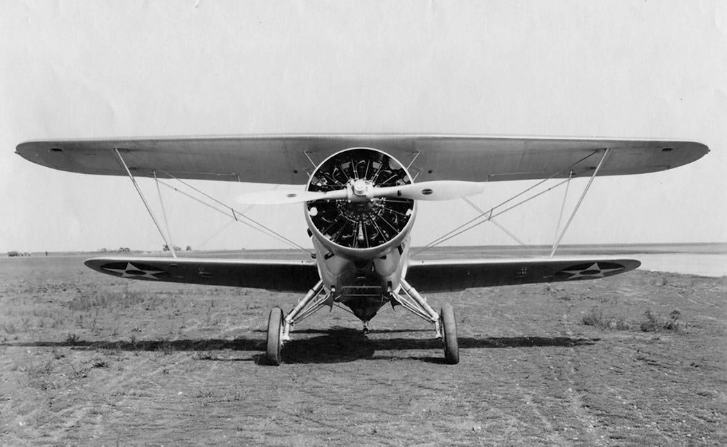
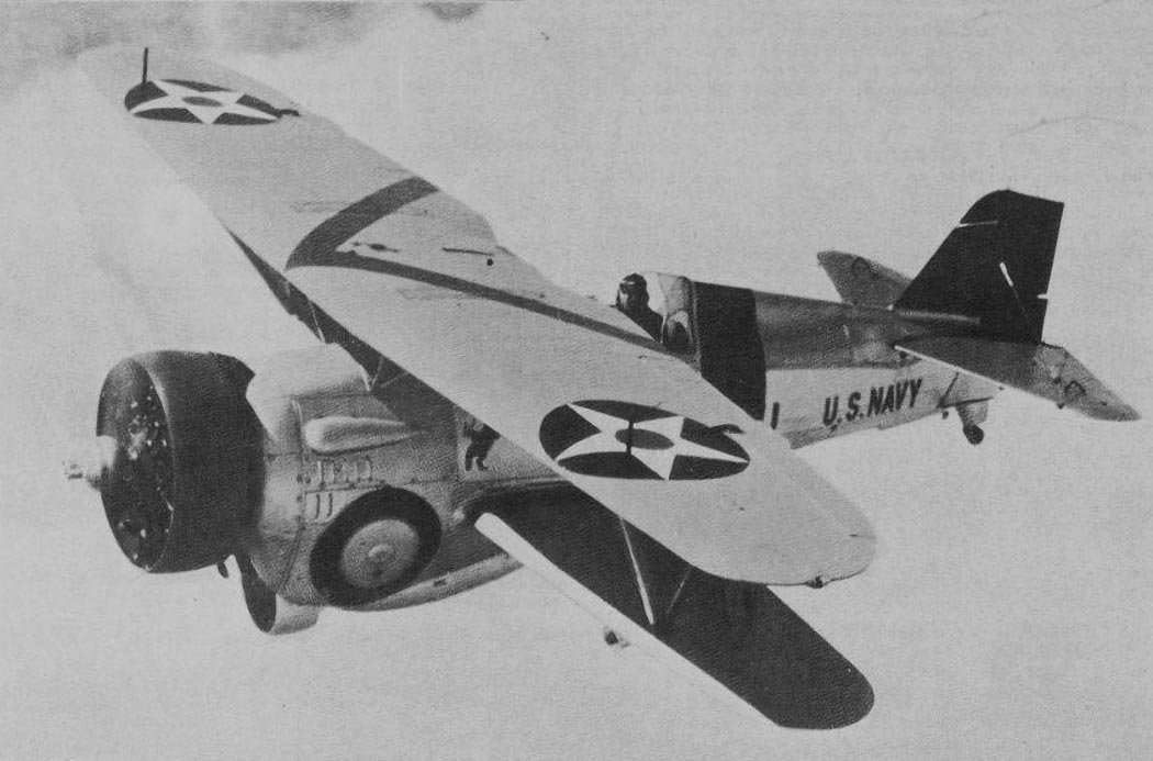
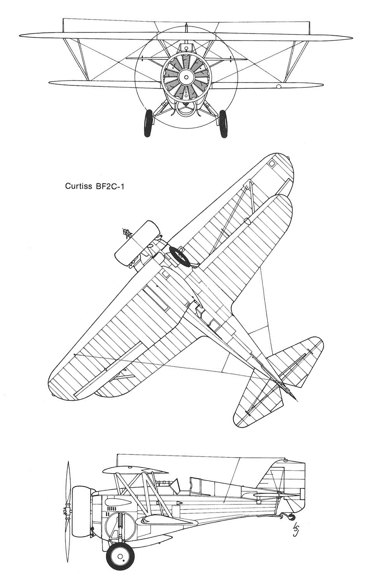
The aircraft was a single-engine, single-seat carrier-based fighter-bomber of mixed construction with retractable landing gear. The fuselage was functionally divided into three parts: front (nose), middle (central), and rear (tail). The fuselage structure was a truss, typical of all previous fighters from the company, consisting of a welded steel tube frame. Duralumin L-shaped stringers were used for the longitudinal elements of the central and tail sections of the fuselage.
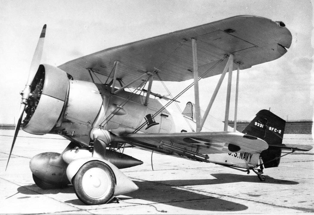
In the forward part of the fuselage, the engine was mounted on a motor frame with instruments and components for the fuel and oil systems. The engine was covered by a quickly removable NACA-type duralumin cowling. Between the pilot’s cockpit and the engine were the oil tank, two fuel tanks, the main landing gear retraction bays, and machine guns with ammunition boxes. The landing gear retraction and extension mechanism was attached to a main bulkhead. Below, in the landing gear area, the fuselage had a central recess with holders for a drop tank or a 227-kg bomb. The front fuselage section was covered by quickly removable duralumin panels, providing convenient access to the machine guns, oil and fuel tanks, and the main landing gear retraction/extension mechanism.
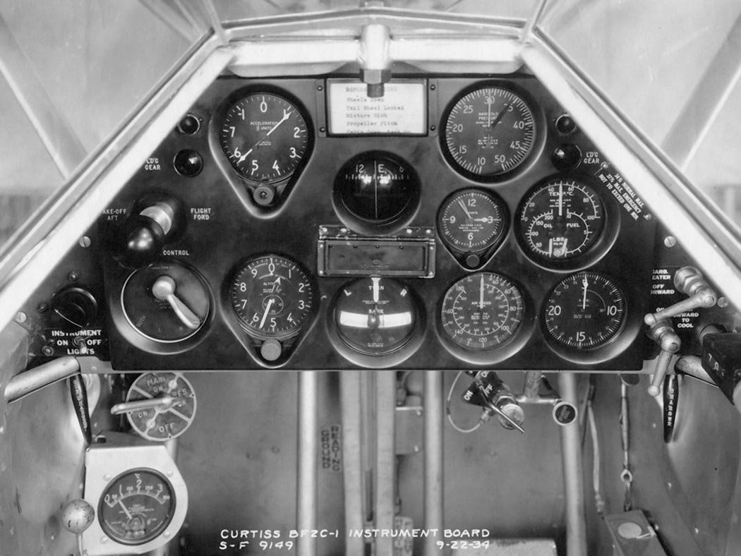
The semi-enclosed pilot’s cockpit was located in the central part of the fuselage. In front, the pilot was protected by a windscreen consisting of three rectangular plexiglass panels. A telescopic sight was mounted on two struts in front of the windscreen. To the side, the pilot’s head was covered by a canopy that could slide backward if needed. The height-adjustable pilot’s seat consisted of two profiled duralumin parts. The seat’s headrest had a soft, leather-covered cushion. There was no armor. Instrument equipment was located on the central instrument panel and on the central lower panel, the so-called “beard.” Some controls and equipment (e.g., engine throttle lever, stabilizer trim wheel) were located on the sides of the cockpit. The covering of the central part of the fuselage was fabric.
Immediately behind the pilot’s cockpit began the tail section of the fuselage. Its upper part formed a fairing over the pilot’s headrest, covered by duralumin panels. Under a removable panel of this fairing, rescue equipment was stored—an inflatable rubber raft, provisions, drinking water, and signal flares. In the lower part of the compartment behind the cockpit, radio units were installed; for servicing, a rectangular quick-release hatch was provided on the left side of the fuselage. The fin and stabilizer with rudder and elevators, as well as the tail skid wheel strut, were attached to the tail section of the fuselage.
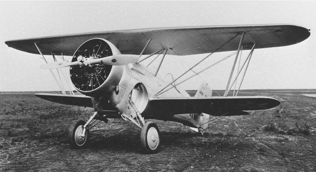
The aircraft’s wing was of biplane design and had an all-metal structure. The upper wing consisted of a center section and outer panels. The wing structure was formed by two box-type duralumin spars and a set of metal ribs. At the wingtips, in special recesses, balonetts (rubberized fabric bags) were stored to ensure the aircraft’s buoyancy during an emergency water landing. The pilot inflated the balonetts with compressed air using a valve located to the right of his seat. The upper wing’s center section had a cutout at the trailing edge to improve visibility of the upper hemisphere. The lower wing consisted of right and left panels and differed little in construction from the upper wing. Each lower wing panel had two holders for 45-kg bombs. The upper and lower wings were connected by two N-shaped struts. The upper wing was attached to the fuselage by similar struts. A pitot tube for the airspeed indicator was attached to the right wing strut.
Wing bracing wires were steel, cable, and doubled. Ailerons were located only on the upper wing. Aileron control was rigid, through push rods running to the ailerons from the lower wing. The wing skin was fabric. The ailerons themselves had duralumin skin. The empennage was of mixed construction. The structure, consisting of spars and ribs, was made of aluminum alloy. The skin of all tail surfaces was fabric. The rudder was designed with aerodynamic horn balance. Trim tabs were installed on both the rudder and elevators. The stabilizer design allowed its angle of incidence to be changed by a screw mechanism. To ensure the necessary rigidity, the stabilizer and fin were braced together by cable wires. Control of the flight surfaces was via cables.
The aircraft’s powerplant included a nine-cylinder Wright R-1820-04 Cyclone air-cooled engine. Most aircraft lacked an exhaust manifold; each cylinder was equipped with an individual exhaust pipe, directing exhaust gases away from the fuselage into the oncoming airflow. Engine control was managed by a throttle lever attached to the left side of the pilot’s cockpit. The aircraft were equipped with Hamilton Standard two-bladed metal controllable-pitch propellers. Fuel was stored in two unprotected fuselage fuel tanks with a total capacity of 418 liters. The front lower 209-liter tank was located immediately behind the main bulkhead and the main landing gear strut retraction bays. The rear upper tank of the same capacity (209 l) was positioned slightly above the front one. They were not connected to each other and had separate filler necks. Fuel was drawn alternately from the front and rear tanks. Their placement near the center of gravity did not disrupt the aircraft’s balance or affect its controllability. An additional suspended 189-liter tank could be installed in the lower part of the fuselage. For the engine’s oil system, a 34-liter tank was installed immediately behind the engine, in front of the fuel tanks.
The landing gear was retractable, with a tail skid wheel. The main landing gear struts were of a pyramidal type with oleo-pneumatic shock absorbers. The landing gear retraction and extension system was typical for early American aircraft with retractable landing gear from the first half of the 1930s. Retraction was achieved by pulling the landing gear struts into the fuselage using a chain drive operated by a handwheel on the left side of the cockpit. The wheels were stowed in special recesses on the side panels of the fuselage. The struts were attached to a reinforced main bulkhead, which also served as a firewall. The main landing gear wheels were equipped with air-actuated drum brakes. The freely swiveling tail wheel strut had rubber cushioning.
The aircraft’s armament consisted of bombing and gun armament. The latter was represented by two synchronized fuselage-mounted 7.62-mm Colt-Browning machine guns with an ammunition load of 600 rounds per gun. Small bombs of 45.3 or 52.6 kg caliber could be carried on four bomb racks. One 227-kg bomb could be suspended on the central under-fuselage hardpoint.
Technical Specifications
| Modification | BFC-2 |
| Wingspan, m | 9.60 |
| Length, m | 7.62 |
| Height, m | 3.23 |
| Wing area, m2 | 24.34 |
| Empty weight | 1378 |
| Maximum takeoff weight | 2104 |
| Engine type | 1 Piston engine Wrighte R-1820-78 |
| Power, hp | 1 x 700 |
| Maximum speed, km/h | 330 |
| Cruising speed, km/h | 274 |
| Practical range, km | 860 |
| Combat range, km | 451 |
| Maximum rate of climb, m/min | 668 |
| Service ceiling, m | 7400 |
| Crew, crew members | 1 |
| Armament: | 2 synchronized 7.62-mm machine guns, 1 x 227-kg bomb located under the fuselage, and 4 x 51-kg bombs on underwing pylons. |
Image and diagram gallery of the Curtiss BFC-2 Goshawk
 BFC-2 Goshawk |
 BFC-2 Goshawk |
 BFC-2 Goshawk |
 BFC-2 Goshawk |
 BFC-2 Goshawk |
 BFC-2 Goshawk |
 BFC-2 Goshawk |
 BFC-2 Goshawk |
 BFC-2 Goshawk |
 BFC-2 Goshawk |
 BFC-2 Goshawk |
 BFC-2 Goshawk |
 BFC-2 Goshawk |
 BFC-2 Goshawk |
 BFC-2 Goshawk |
 BFC-2 Goshawk |
 BFC-2 Goshawk |
 BFC-2 Goshawk |
 BFC-2 Goshawk |
 BFC-2 Goshawk |
 BFC-2 Goshawk |
 BFC-2 Goshawk |
 BFC-2 Goshawk |
 BFC-2 Goshawk |
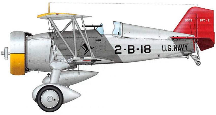 BFC-2 Goshawk |
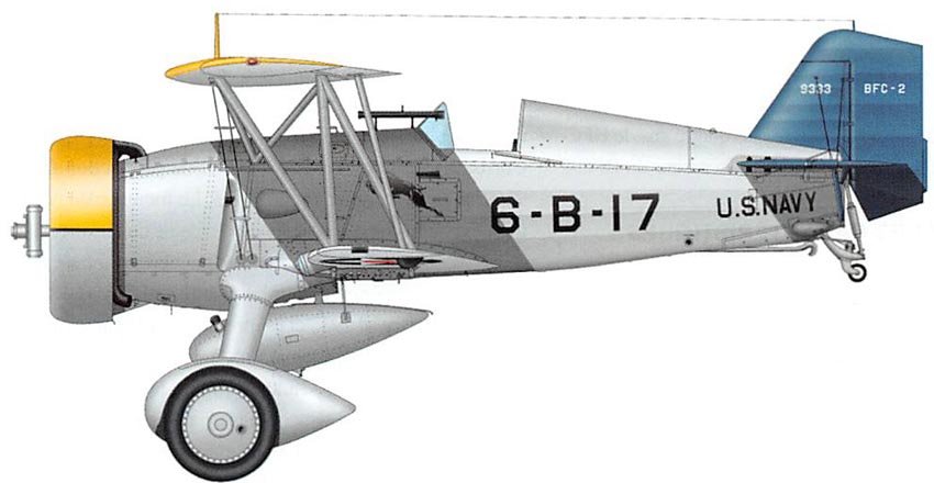 BFC-2 Goshawk |
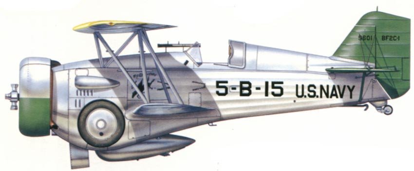 BFC-2 Goshawk |
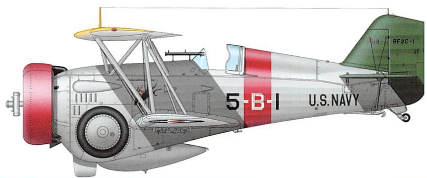 BFC-2 Goshawk |
ArchivoAéreo Editorial Team
A group of aviation researchers and enthusiasts dedicated to documenting and preserving global aeronautical history. All articles are reviewed to ensure historical accuracy.
Sources & Accuracy
The information presented in this technical sheet has been compiled from declassified flight manuals, historical archives, and specialized literature. While we strive for maximum accuracy, some performance data may vary depending on the specific variant or operational conditions.