Boulton & Paul P.12 Bodmin
The Ministry of Aviation’s procurement policy involved issuing specifications to large firms. Submitted proposals were evaluated by the research department after the contracts department rendered them anonymous, as most designers had characteristic features in their work. The two best projects received contracts for prototype production.
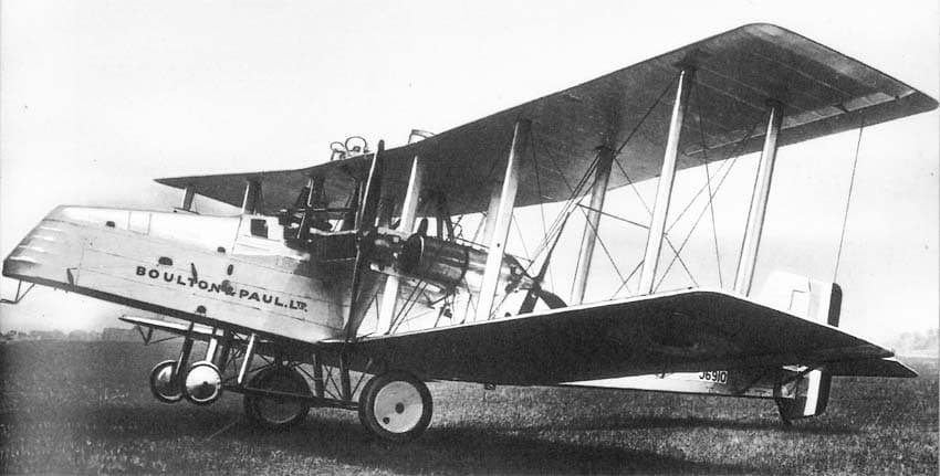
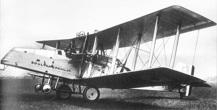
In 1922, Boulton & Paul built two prototypes of a proposed “mail plane,” which the Ministry of Aviation used for experimental flights. In reality, if successful, the aircraft was planned for use as a medium bomber. In this instance, the concept of creating a multi-engine aircraft with engines located inside the fuselage, driving propellers on the wing, was being investigated.
The concept originated at the Bristol company, where Frank Barnwell proposed building a version of his enormous Braemar triplane, equipped with two 1500 hp steam turbines in a fuselage engine compartment. The development costs for such a revolutionary idea were too high, but the Ministry of Aviation was interested in the “internal engine room” concept as a means of ensuring safety for long-distance flights.
They proposed a design with four Armstrong Siddeley Puma engines installed inside the fuselage. Specification 1/20 was developed for the so-called “spare parts carrier”—another Ministry of Aviation euphemism—and a contract was issued for the manufacture of a prototype, resulting in the Bristol Tramp triplane with four Puma engines located in the fuselage.
A separate specification, 9/20, was released for a “mail plane” that was to be smaller than the Tramp. Two projects won the order under this specification: the single-engine Parnall Possum and the twin-engine Boulton & Paul Bodmin. The Bodmin was a biplane, very similar, as far as the concept allowed, to the Bourges.
Innovative Design and Construction
The Bodmin featured two Napier Lion engines driving four propellers: two tractor and two pusher. The airframe was of all-metal construction. The larger Tramp was ordered with a tender price of £23,000, whereas the Bodmin’s tender price was only £20,000.
Much credit for the development of the steel spars and other structures goes to Harold John Pollard, who previously (after graduating from University College Nottingham) worked at Vickers. He was hired by North as an assistant specialist for the development of metal structures and later moved to Bristol to perform similar work.
The “engine room” concept was an ideal opportunity for John North to demonstrate the advantages inherent in all-metal construction, particularly the potential for weight savings. The airframe was entirely made of high-strength drawn or stamped sheet steel, connected to tubes with a new Boulton & Paul-developed interlocking joint system.
Fabric covering remained everywhere, although the Ministry of Aviation was convinced by John North’s arguments that building the Bodmin from steel would result in a structure 10% lighter than wood and that the skin should be of corrugated sheet steel, using the method developed in Germany by Junkers.
The transmission, connecting shafts, and their support structures—which, for installation reasons, had to be independent of the wing structure—added weight to the aircraft. Furthermore, the engine placement caused greater loads on the wings than in a conventional layout, requiring them to be stronger and, consequently, heavier.
Onboard Safety and Maintenance
The layout’s goal was to create a safe aircraft. A mechanic could work with the Napier Lion engines in the engine compartment, which was illuminated by both electric and sunlight from windows. All engine monitoring instruments were located in the engine room: tachometers, oil temperature and pressure gauges, and necessary controls.
Moreover, each engine could be stopped without causing any asymmetric thrust. The front engine drove two tractor propellers, and the rear engine drove two pusher propellers; the propellers were positioned opposite each other to avoid torque-induced yawing. The aircraft was capable of flying at cruising altitude with one engine operating.
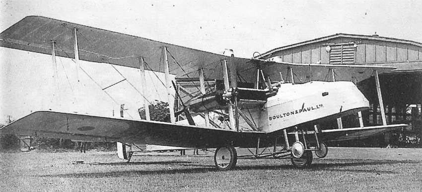
The main landing gear struts were equipped with oil-pneumatic shock absorbers. Their design was quite novel, befitting the rest of the aircraft. Oil pressure in the struts could freely rise to a certain limit and then be released by opening spring-loaded safety valves in the piston and cylinder head. At rest, the aircraft’s smooth movement was maintained not by springs, but by air.
Air was pumped into the tire bladders with a regular pump to a pressure of 60 psi (4.218 kg/cm²), and expanded after takeoff to adjust the distance between the struts to the landing position. A pressure of 60 psi was considered sufficient to cushion bumps during taxiing. The main front wheels were two small wheels designed to prevent nosing over during landing.
Further safety features were later incorporated into the design. There were six fuel tanks, each of which could be isolated from the fuel system in case of damage. The radiators were made in six sections, each of which could be shut off in case of a leak. The radiators were positioned to wrap around the extended shafts and fuel tanks, forming a closed, integrated structure between the wings.
The engine exhaust pipes were fitted with specially designed flame arrestors to protect the rear gunner, whose workstation was located directly behind the engine compartment. This indicates that this so-called “mail plane” was, in fact, a bomber prototype. Its long nose and auxiliary nose wheels were also designed for the later installation of heavy-calibre armament, although the nose had a streamlined top position for a conventional Scarf ring.
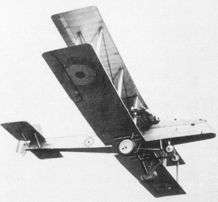
The wings, without overhang, were a three-bay design with a span of 70 ft (21.336 m) and square wingtips. Thanks to the work of Boulton & Paul mathematician Otto Glauert, they had a relatively high aspect ratio. Professor Prandtl of Göttingen had mathematically confirmed, even before the war, Lanchester’s work, which showed that wing drag consists not only of its profile shape but also an additional part dependent on the relative aspect ratio.
Glauert’s brother worked on the same theory at Farnborough, and he approached John North with its advantages, confirmed by the flight tests of the P.7 Bourges. The aircraft was over 53 ft (16.154 m) long, most of which accounted for the elongated nose, shaped like the bow of an inverted boat. The pilot sat in an open cockpit located in front of the wing.
The horizontal tailplane had tips similar to the wingtips; the fin and rudder had a greater rake angle compared to John North’s previous designs.
Test Flights and Operational Challenges
In early 1924, Frank Courtney was responsible for the first flight of the first Bodmin prototype, J6910. Since the machine was designated a “mail plane,” there were no military restrictions on press interest. He was bombarded with questions about the possible failure of the complex drive shafts, gears, and clutches, and what they would do to the airframe if they broke apart and scattered.
After a first flight that went smoothly, and then several more, journalists took Courtney to lunch in Norwich and were probably disappointed that his stories about the first flight in such a “dangerous” aircraft did not turn out to be sensational. However, journalists eventually got a story of a similar kind.
As Courtney was leaving the restaurant, he was knocked to the ground by a delivery boy on a bicycle; his glasses broke, scratching the pilot’s entire face. In an interview, Courtney stated that he felt much safer in the air in the “dangerous” Bodmin than on the ground.
In fact, the Bodmin flew very well, although it faced cooling and power transmission problems. The engine room was noisy and stuffy, but it had one advantage for the mechanic. In this stuffy, enclosed world, he often remained oblivious to the problems faced by the poor pilots in their open nose cockpit. Courtney wrote about one test flight: “I have vivid recollections of Inspector Martin busily tending to the mechanisms in the engine room while I, in the Bodmin with low fuel, tried to get back to Mousehold in a thunderstorm.”
The novel landing gear design failed on February 11, 1924. While taxiing at 6-10 mph (9.654 – 16.09 km/h) across Mousehold to the takeoff position, the aircraft went over a hump, veered left, and crashed onto its right side. It was determined that the existing travel of the hydraulic struts was insufficient to cope with such bumps, except at very slow or, conversely, higher speeds.
It seemed the only possible fix was to fully fill the struts with oil before each flight and level all such humps at Mousehold. Two Bodmin prototypes were built—J6910 and J6911. Sea-level speed was 116 mph (186.644 km/h)—a disappointing figure compared to its contemporary, the Boulton & Paul P.15 Bolton—and the ceiling of 16,000 ft (4876.792 m) also fell short of what one would expect from a conventional aircraft.
It was believed that this was due to layout drawbacks, meaning the extra weight outweighed the advantages, which were primarily in the area of safety. The Bodmin could only lift a useful operational load because the additional weight of the engine transmission was offset by the lighter weight of the Boulton & Paul, which was achieved through all-metal construction—lighter compared to wood.
North calculated that 20% had been saved compared to the initial 10%. The work was successful, but the concept died. Boulton & Paul learned a great deal about the production of steel structures, which would serve them well in the future.
Technical Specifications
| Modification | Bodmin |
| Wingspan, m | 21. 34 |
| Length, m | 16. 27 |
| Wing area, m2 | 111. 90 |
| Empty weight | 3592 |
| Normal takeoff weight | 4 990 |
| Engine type | 2 Piston engines Napier Lion |
| Power, hp | 2 x 450 |
| Maximum speed, km/h | 1 87 |
| Cruising speed, km/h | 155 |
| Rate of climb, m/min | 243 |
| Service ceiling, m | 4877 |
| Crew, crew members | 3-4 |
| Armament | It was planned to install two 7.7-mm Lewis machine guns on a movable Scarff turret in the nose and tail sections. |
Image and diagram gallery of the Boulton & Paul P.12 Bodmin
 P.12 Bodmin |
 P.12 Bodmin |
 P.12 Bodmin |
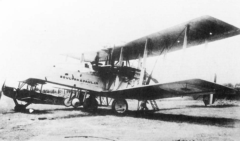 P.12 Bodmin |
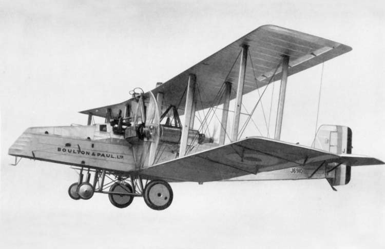 P.12 Bodmin |
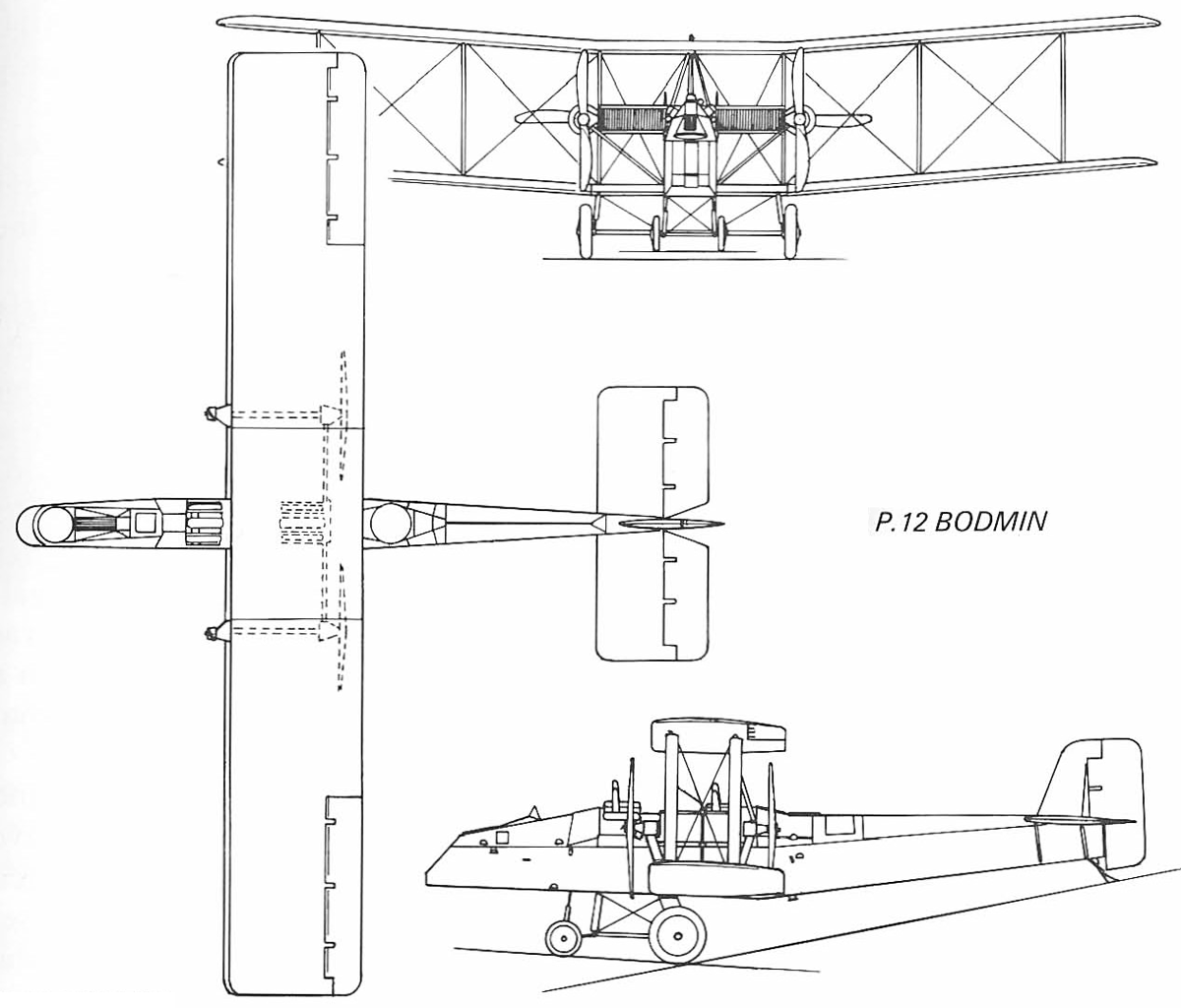 P.12 Bodmin |
Equipo Editorial de ArchivoAéreo
Grupo de investigadores y entusiastas de la aviación dedicados a documentar y preservar la historia aeronáutica mundial. Todos los artículos son revisados para garantizar precisión histórica.
Fuentes y Rigurosidad
La información presentada en esta ficha técnica ha sido compilada a partir de manuales de vuelo desclasificados, archivos históricos y bibliografía especializada. Aunque nos esforzamos por mantener la máxima precisión, algunos datos de rendimiento pueden variar según la variante específica o las condiciones operativas.