The previous part of the monograph concluded with the disaster of Australia’s first twin-engine combat aircraft, the CA-4 Wackett Bomber, on January 15, 1943, which claimed two lives. The Australian government and the RAAF had set an ambitious task: to achieve independence from foreign aircraft supplies in the upcoming world war. However, for various reasons, the development of the multi-role CA-4 dragged on, with testing continuing even four years after Australia’s entry into the war.
During these tests, several unacceptable characteristics were identified, largely due to a lack of design experience. In 1942, chief designer Wing Commander L. J. Wackett, after whom the prototype was named—the Wackett Bomber—began work on a heavily modernized version of the CA-4. Despite significant official support, the time factor had a major impact on this situation. The new version, designated CA-11 and named Woomera, was expected to demonstrate immediate success, with mass production commencing directly after factory trials.
Development and Early Challenges
Otherwise, there was little hope that the aircraft would see combat. This was not because the end date of the war was known, but because the flight characteristics specified in 1939 would be insufficient four or five years later. Although RAAF command issued a contract on March 8, 1942, for the serial production of one hundred and five CA-11 units (Specification No. 242; CA-4 prototype specification No. 241), construction of the second multi-role prototype was suspended. This was due to the ongoing production of CA-6 Wackett trainers, light multi-role CA-16 Wirraways, and the commencement of serial production of CA-12 (-13, -14, and -19) Boomerang fighters.
Moreover, by this time, Australia was no longer an isolated country forced to rely on its own capabilities, as it had been in the late 1930s. Aircraft were now being supplied by both Great Britain and the United States. In 1942, excellent American bombers like the North American B-25 Mitchell and Douglas A-20 Boston began entering RAAF service, with other types of aircraft, including single-engine fighters and four-engine heavy bombers, also expected. Additionally, Beaufort bombers had entered serial production, heavy Beaufighter fighters were being prepared for mass production, and discussions were underway for the possible procurement of the famous Mosquito.
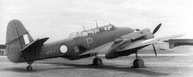
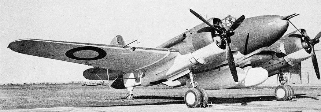
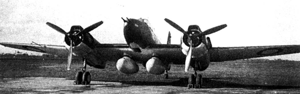
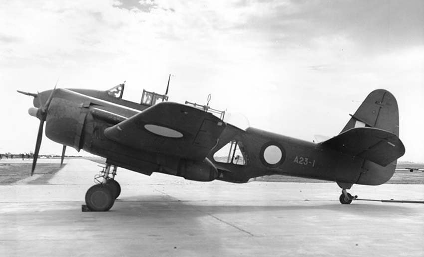
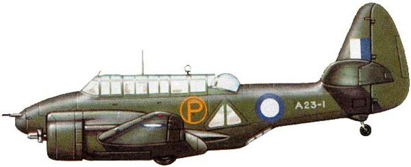
The urgency for rapid CA-11 development receded into the background, especially after it became clear that the configuration of the basic CA-11A version, intended for more powerful engines, had not yet been finalized. The second bomber, the CA-11 Woomera (military number A23-1), designed by L. J. Wackett, left the CAC corporation’s factory workshop in Fishermans Bend in mid-1944. At first glance, the CA-11 differed from its predecessor in camouflage: dark green on the upper and side surfaces and light blue on the lower ones.
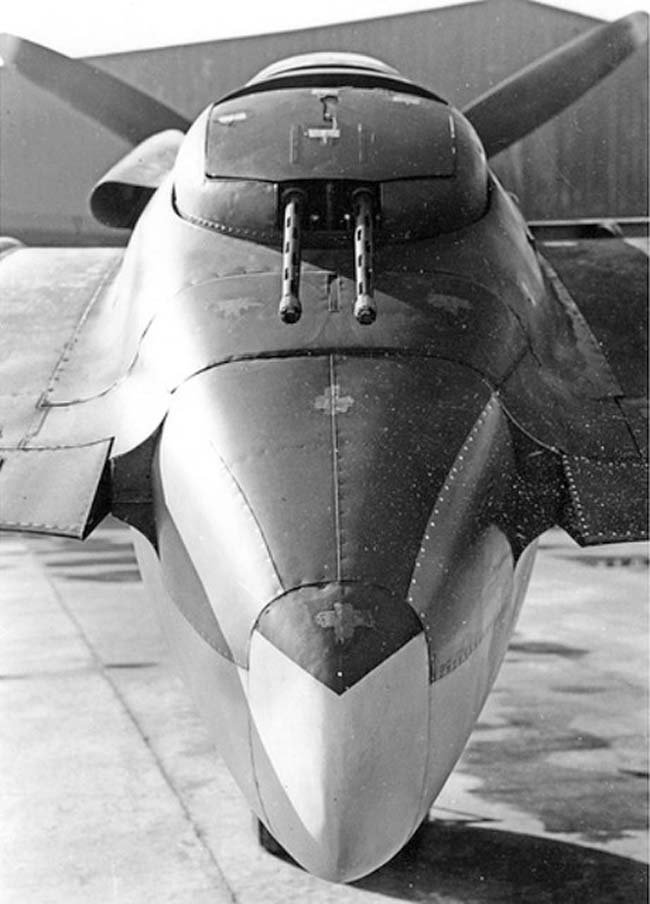
Upon closer inspection, it was noticeable that the wing center section had a longer chord length, and the outer wing panels had a greater dihedral angle. The tail unit and crew cockpit glazing were also enlarged. Significant changes occurred in the aircraft’s armament: two 20-mm cannons and two 7.7-mm machine guns were installed in the nose section of the fuselage.
Flight Testing and Setbacks
On July 7, 1944, the CA-11 prototype (A23-1) made its maiden flight. CAC test pilot G. R. Board was in the cockpit, with 200 pounds (91 kg) of ballast in the rear cockpit, bringing the takeoff weight to 7332 kg. That Friday, the weather near Melbourne was exceptionally unsuitable for aviation—strong winds and a completely overcast sky with dark clouds, whose lower boundary was at 600 meters. Perhaps the weather itself foreshadowed subsequent events.
During taxiing procedures in preparation for the first flight, Board discovered that the main landing gear wheel brakes worked perfectly, unlike those installed on the CA-4. After takeoff, the rudder acted lightly and effectively. To protect engine cylinders from overheating and in case of a blocked regulation system, cooling flaps were installed around the perimeter of the rear parts of the engine cowlings. The only concern was the oil temperature rising above the red line, even with the oil cooler flap fully open.
However, that Friday brought continuous misfortunes. In flight, the cap of the machine-gun turret on the right nacelle unexpectedly flew off, and almost simultaneously, the radio failed. The aircraft began to vibrate, the throttle position changed spontaneously, and Board started to get a little nervous. After deciding to return and a short climb, the oil temperature crossed the red line, threatening a fire. Yet, smoke and a foul odor appeared not from the engines but in the cockpit.
The pilot, not wanting to suffocate or lose orientation, opened the cockpit canopy and used an oxygen device. After this, Board, without hesitation, headed for Fishermans Bend. During landing maneuvers, as the speed dropped to 194 km/h, low aileron effectiveness was discovered: to level the aircraft relative to the horizon, the ailerons had to be deflected fully downwards! Fortunately, the 35-minute flight ended without additional incidents, and Board safely brought the machine to a complete stop.
The aircraft was returned to the corporation’s workshop for repairs. It was discovered that the smoke in the cockpit was caused by “burning out” of the cockpit and forward armament compartment heating. Work was carried out on the oil radiator, engine cowling skin, and ailerons, and the radio was repaired. On July 10, 1944, Board flew the CA-11 for the second time, remaining aloft for 80 minutes. This time, there were no defects, and only minor vibrations were observed. Board even ventured (and the aircraft performed normally) horizontal flight and turns with one engine shut down, then the other.
The third flight, also performed by Board alone with ballast in the rear cockpit, took place on July 13, 1944. On the same day, complex tests were conducted, including reaching stall speed and performing dives. In a dive, after exceeding 400 km/h, the aircraft’s controls “stiffened,” and the pilot had to assist by throttling the engines. Difficulties then arose during landing. On the ground, it was found that the elevator trim tab was broken and unresponsive to control inputs. Thus, the aircraft was again sent to the workshop for corrections.
Six days later, the fourth flight took place. The pilot was still not satisfied. By this time, RAAF pilot Squadron Leader D. R. Cumming had joined the test flights. In the flight on July 22, 1944, under Board’s control, wool tufts were taped to the engine nacelles and tail unit to determine the airflow pattern around various parts of the aircraft. As a result of subsequent changes, for which the aircraft was once again sent to the workshop, the rear parts of the engine nacelles were lengthened, and the machine-gun turret fairings were modified.
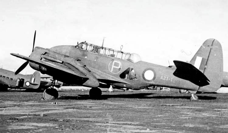
The horizontal stabilizer also changed, receiving a significant dihedral angle, as did the elevator trim control system. Simultaneously, the aircraft underwent cosmetic changes—all its surfaces were painted green. By the date the aircraft was transferred to the RAAF’s 1st Air Performance Unit in Laverton (November 21, 1944), 19 factory test flights had been completed. With the exception of one flight, G. R. Board was always in the cockpit.
Program Cancellation and Legacy
By this time, the CAC corporation had almost completed the construction of the third prototype, the A23-2, a production variant of the CA-11A. This aircraft differed from previous prototypes in its power plant. Designers planned to install 1350 hp (992 kW) Pratt & Whitney R-2000 Twin Wasp engines, which were not yet supplied from the USA but whose licensed production had already begun in Australia. However, in September 1944, the program was abruptly terminated. The Australian government, with the consent of RAAF command, canceled the CA-11 program.
This meant not only scrapping the unfinished A23-2 prototype but also a cooling of interest in detailed flight tests. In December 1945, after the official RAAF trials of the CA-11 concluded, the aircraft was transferred to the 1st Central Recovery Depot in Werribee. On April 11, 1946, permission was granted for the CA-11’s dismantling. The “government-owned” parts of the aircraft (instrumentation, engines, armament, and other equipment) were returned to the RAAF, while the rest, including the airframe, was written off.
Following the completion of design work on the CA-11 and the commencement of its testing, Wing Commander L. J. Wackett was involved in another, this time much more successful, project. He traveled to the USA to coordinate technical specifications with North American for the licensed production of P-51D Mustang fighters. Additionally, Wackett did not forget his multi-role Woomera aircraft: during a meeting with Boeing representatives, he managed to reach an agreement to adapt the remote armament control system he had developed for the CA-11A to the B-29. After the war, the CAC corporation attempted to revive the project, re-profiling it as a multi-role trainer, but without much success.
In assessing the characteristics and capabilities of the CA-4 and CA-11, much remains unanswered. However, one thing is certain: despite the practical failure, conceptually the idea was sound, and in countries with more experienced and developed aircraft manufacturing industries, a very successful combat aircraft could have been produced in a shorter time.
Technical Description
The Commonwealth Aircraft Corporation CA-4 Wackett Bomber and CA-11 Woomera multi-role combat aircraft were cantilever monoplanes of all-metal construction (with minimal use of other materials) featuring retractable main landing gear. These multi-role combat aircraft were primarily intended to serve as bombers (for battlefield support), torpedo bombers, and reconnaissance aircraft.
The structural frame of the aircraft fuselage consisted of a rectangular-section truss structure, welded from chromoly steel tubes. An ovoid-shaped duralumin monocoque was attached to this base. The rounded lower section effectively formed an under-fuselage gondola, housing the workstation of the third crew member (bombardier-navigator-gunner). This gondola was formed by attaching a semi-monocoque structure to the truss. The upper rounded part of the fuselage was made of duralumin sheets. Behind the crew cabin was a compartment for a rubber life raft. In the fuselage, the side surfaces behind the crew cabin were removable panels, made of fabric-covered plywood and mounted on wooden auxiliary frames.
The aircraft crew comprised three individuals: the pilot (first crew member), seated in the forward “fighter-type” cockpit; behind him was the second crew member (co-pilot-gunner), whose workstation was equipped with a partially furnished instrument panel and controls (pedals and a folding control stick). Another task of the second crew member was to protect the aircraft’s rear hemisphere via two remotely controlled turrets, installed in the rear parts of the engine nacelles. For aiming and firing, the aircraft was equipped with a collimator sight. For the CA-4, the crew member had to stand up and face backward, while for the CA-11, they only had to turn backward. The third crew member (bombardier-navigator-gunner) had a workstation inside the aircraft fuselage. Triangular windows, also serving as entry/exit doors, were located on the sides of their cabin. For machine-gun firing and bomb/torpedo drops, they descended into the under-fuselage gondola.
The pilot entered his cockpit, equipped with a rearward-sliding canopy, from the left side of the fuselage, which featured integrated footrests. With some effort, he could also enter from the right side. The front armored glass was 3 inches (76.2 mm) thick and measured 254 × 350 mm. For access to the rear cockpit, integrated footrests were present on both sides of the fuselage. The co-pilot was intended to control the aircraft in emergencies: if the pilot was wounded, during long flights to allow the main pilot to rest, or in case of Sperry autopilot failure. The co-pilot’s primary role in the CA-11 was radio operation, for which they would turn their seat backward (in the CA-4, the radio operator was to be the third crew member).
Mounting points for attaching the root sections of the wing center section were installed in the lower part of the fuselage truss. In the rear of the fuselage were attachment points for the tail unit and tail wheel landing gear. Technologically, the aircraft’s cantilever wing consisted of a two-spar center section and two outer panels. The center section was integral and had a smoothly varying chord length across its span, increasing from the tips towards the root sections. The leading edge of the center section had a slight sweep, while the trailing edge of the wing was straight.
The outer wing panels had nearly straight trailing edges and leading edges with significant sweep. The rounded wingtips of the outer panels were made of wood and were removable. All other wing parts were metallic. Closer to the ends of the wing center section, which was attached to the lower part of the fuselage truss, were the engine nacelles, which had a semi-monocoque construction. Outside the nacelles, at the ends of the wing center section, were attachment points for the detachable outer wing panels.
Handley Page slots were installed on the leading edge of the wing center section; on the trailing edge of the center section, on each side of the fuselage, were two split flaps, attached to the rear auxiliary spar. On takeoff, the flaps deflected 17°; during landing, 45°; and 75° when functioning as dive brakes. The longer flaps were located closer to the aircraft’s axis between the fuselage and the wing nacelles; the shorter flaps were between the engine nacelles and the ends of the center section. A third pair of flaps was located between the root sections of the outer panels and the ailerons.
Above the flaps were dive brake grilles, attached to the same auxiliary spar and raised upwards. In a dive, to reduce aircraft speed, the dive brakes deflected 60°. Two pairs of dive brakes were installed on the upper wing surface: the first pair between the fuselage and the engine nacelles, and the second on the outer panels above the outboard flaps (there were no dive brake grilles above the outboard flaps of the center section). Control of the dive brakes and flaps was achieved via a hydraulic drive.
Ailerons, with a duralumin structure and fabric covering, were installed on the outer wing panels. Landing lights were mounted on the leading edge of each panel; a Pitot tube was installed on the right panel. The tail unit of the first variant (CA-4) had the same shapes as the Wirraway multi-role aircraft, whereas on the CA-11, it was reduced (the vertical stabilizer acquired a more conical shape). The fin and stabilizer (which could not change its angle of attack) were cantilever, having an all-metal two-spar construction. The elevators and rudder had a duralumin structure and fabric covering. The elevators were equipped with trim tabs, and the rudder had static and dynamic compensation.
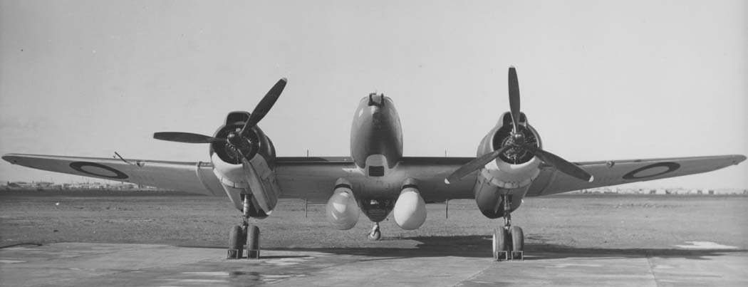
The aircraft’s landing gear featured two main and one tail strut. The main struts were each equipped with two side-by-side wheels and were retractable. The wheels were fitted with brakes. The main struts retracted rearward into bays located in the lower parts of the engine nacelles. In the retracted position, the main landing gear wheels protruded by approximately one-third, which was intended to prevent damage to the aircraft fuselage during an emergency landing and simplify the nacelle design. The tail strut was non-retractable; its wheel was enclosed in a hinged, rigidly fixed fork. Each main landing gear door was split longitudinally, as two 113 kg bombs were mounted on suspension points behind the engines within the engine nacelles.
The power plant consisted of two fourteen-cylinder air-cooled radial Pratt & Whitney R-1830 Twin Wasp engines; the CA-4 was equipped with the S3C-G version, and the CA-11 with the S3C3/4-G version. The S3C-G engine developed a takeoff power of 1100 hp (809 kW) at 2700 rpm, while the S3C3/4-G engine produced 1200 hp (882 kW); nominal power at 2300 meters altitude and 2250 rpm was 950 hp (698 kW) and 1050 hp (772 kW) respectively. At 4200 meters and 2250 rpm, both versions developed 700 hp (515 kW). The engine, weighing approximately 665 kg, had a diameter of 1224 mm and a total cylinder volume of 1830 cubic inches (30 liters). The engine was equipped with a single-stage, single-speed supercharger and a planetary reduction gear with a ratio of 0.5625:1, which reduced propeller speed. The CA-4 prototype used an automatic Curtiss propeller with electrically controlled pitch change mechanism; the propeller diameter was 3.5 meters. The CA-11 was equipped with three-bladed de Havilland propellers, featuring a hydraulic pitch change system. Later, the CA-11 received Hamilton propellers. In both cases, the propeller diameter was 3.5 meters.
Fuel (aviation gasoline with 95/100 octane rating) was stored in integral fuel tanks located in the wing center section between the spars. On each side of the fuselage, there was one main tank with a capacity of 478 liters (No. 1) and one main tank with a capacity of 450 liters (No. 2). Behind the engine nacelles were two additional fuel tanks (Nos. 3 and 4), each with a capacity of 282 liters. The total internal fuel capacity (2420 l) could be increased by installing two 1333-liter external drop tanks on the torpedo pylons.
Armament. The fixed forward-firing armament (the pilot aimed the entire aircraft at the target using a classic or collimator sight) for the CA-4 prototype consisted of four Vickers K machine guns, later replaced by Browning Mk.II machine guns; both types had a caliber of 7.7 mm. For the CA-11 prototype, two 20-mm British Hispano cannons and two 7.7-mm Browning Mk.II machine guns were installed in the nose section. For rear hemisphere defense, two remotely controlled turrets were installed in the rear parts of the engine nacelles, each equipped with two 7.7-mm Browning Mk.II machine guns. The second crew member controlled the turrets, aiming the machine guns at the target using a collimator sight. The third crew member fired a 7.7-mm Vickers K machine gun installed in the lower part of the fuselage.
Since the aircraft did not have an internal fuselage bomb bay, bombs and torpedoes were carried on two pylons or torpedo racks. These could accommodate four 500-kg bombs, or two Mk.XVI torpedoes, or a combination of these loads. Four 113-kg bombs could be carried in the engine nacelles. For training bombing runs, suspension points for eight 11-kg practice bombs were located under each wing panel. The release of bombs and torpedoes was performed by the third crew member, who aimed through the front window of the ventral gondola.
Technical Specifications
| Modification | CA-11 |
| Wingspan, m | 18.04 |
| Length, m | 12.03 |
| Height, m | 4.11 |
| Wing area, m2 | 36.78 |
| Empty weight | 6387 |
| Normal takeoff weight | 9128 |
| Engine type | 2 Piston engines Pratt Whitney Wasp R-2000 Wasp |
| Power, hp | 2 x 1300 |
| Maximum speed, km/h | 454 |
| Cruising speed, km/h | 407 |
| Practical range, km | 3677 |
| Maximum rate of climb, m/min | 637 |
| Practical ceiling, m | 7162 |
| Crew | 3 |
| Armament | two 20-mm cannons and two 7.7-mm Vickers Mk V machine guns. Bomb load: 2 torpedoes, 2 x 113-kg bombs, 8 x 13-kg bombs; or 4 x 227-kg bombs, 2 x 113-kg bombs, 8 x 13-kg bombs; or 2 x 1109 L tanks and 2 x 113-kg bombs, 8 x 13-kg bombs. |
Image gallery of the CA-11 Woomera